Orthogonal plane calibrating method and orthogonal plane calibrating system of relation between laser distance measuring device and end of mechanical arm

A laser rangefinder and calibration method technology, applied in the field of visual measurement, can solve problems such as insufficient constraints and poor repeatability of the hand-eye calibration matrix

Active Publication Date: 2016-03-30
SINOVATION BEIJING MEDICAL TECH CO LTD +1
View PDF10 Cites 20 Cited by
  • Summary
  • Abstract
  • Description
  • Claims
  • Application Information

AI Technical Summary

Problems solved by technology

In the literature [Robotics and Automation, IEEE Transactionson, 1998, 14(3):493-497], the hand-eye calibration method of the laser rangefinder and the manipulator is given in general, but how to transform the coordinates in the manipulator coordinate system The conversion to the coordinate system of the laser rangefinder is not clearly given in this document [Robotics and Automation, IEEE Transactionson, 1998, 14(3): 493-497]. To realize it, readers need to do some creative exploration
And the current method can obtain high accuracy in theory, but in practice, due to insufficient constraints, the repeatability of solving the hand-eye calibration matrix is ​​poor

Method used


Image

  • Orthogonal plane calibrating method and orthogonal plane calibrating system of relation between laser distance measuring device and end of mechanical arm
  • Orthogonal plane calibrating method and orthogonal plane calibrating system of relation between laser distance measuring device and end of mechanical arm
  • Orthogonal plane calibrating method and orthogonal plane calibrating system of relation between laser distance measuring device and end of mechanical arm

Examples


Embodiment Construction

[0105] The present invention will be further elaborated below through specific embodiments in conjunction with the accompanying drawings.

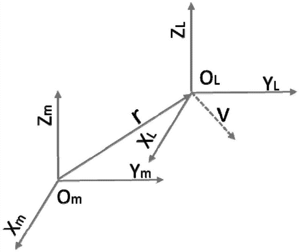
[0106] The coordinate system at the end of the manipulator is O m , X m , Y m and Z m are the three coordinate axes of the coordinate system at the end of the manipulator, and the coordinate system of the laser rangefinder is O L , X L , Y L and Z L They are the three coordinate axes of the laser rangefinder coordinate system. The laser rangefinder coordinate system is only translated by r relative to the coordinate system at the end of the manipulator. The unit direction vector of the laser beam emitted by the laser rangefinder is in the laser rangefinder coordinate is v, such as figure 1 shown.

[0107] The following spatial point coordinates and vectors are represented by 3*1 column vectors, the normal vector is a unit vector, and the unit direction vector of the laser beam is also a unit vector.

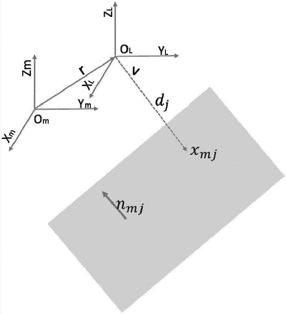
[0108] like figure 2 As sho...


PUM


Abstract

The invention discloses an orthogonal plane calibrating method and an orthogonal plane calibrating system of relation between a laser distance measuring device and an end of a mechanical arm. The laser distance measuring device is fixedly disposed on the end of the mechanical arm, and the calibrating planes, which are orthogonal to each other, are disposed in the space. Under the driving of the rotating translational motion of the mechanical arm, the posture of the laser distance measuring device can be changed, and the distance d measured by the laser distance measuring device can be used to solve the translational vector r and the unit direction vector v of the laser beam, and the calibrating of the space transformation relation between the laser distance measuring device and the end of the mechanical arm can be completed. The reconstruction of the point x of the object in the three-dimensional object can be realized according to the x=r+dv. The transformation relation between the coordinate system of the end of the mechanical arm and the coordinate system of the laser distance measuring device can be determined clearly. By using the calibrating plane as the orthogonal plane and adopting the non-linear optimization method, the coplanarity of the points can be fully used as the constraint condition to solve the calibrating problem of the space transformation relation, and therefore the constraint condition can be added, the errors can be reduced, the noise interference can be reduced, the robustness and the easy implementation of the method can be improved, and the calibrating precision of the space transformation relation can be improved.

Description

technical field [0001] The invention relates to the field of visual measurement, in particular to an orthogonal plane calibration method and system for the spatial transformation relationship between a laser range finder and the end of a mechanical arm. Background technique [0002] With the improvement of the electronic industry level and the development of computer technology and optical sensor technology, machine vision has been widely used in industrial processing, aviation, automobile, ship, entertainment, medical and other fields. [0003] In order to use the robotic arm to complete the stereotaxic electrode implantation operation, it is necessary to register the coordinate system of the robotic arm with the patient's three-dimensional space coordinates. The basis of registration is to establish the transformation relationship between the end of the robotic arm (such as gripper, flange, etc.) and the sensor (camera, structured light equipment, laser rangefinder, etc.),...

Claims


Application Information

Patent Timeline
Patent Type & Authority Applications(China)
IPC IPC(8): G01B11/00
CPCG01B11/00
Inventor 王广志曾柏伟丁辉刘文博吴迪
Owner SINOVATION BEIJING MEDICAL TECH CO LTD
Why Eureka
Try Eureka