Device and method for measuring and calibrating sound intensity

A technology for calibrating devices and sound intensity, applied to measuring devices, measuring ultrasonic/sonic/infrasonic waves, instruments, etc., can solve the problems of increased calibration inaccuracy, high processing and installation requirements, and low accuracy of results, etc., to achieve Convenient instant detection, stable calibration signal, easy to carry effect

Active Publication Date: 2018-10-26
ZHUZHOU TIMES NEW MATERIALS TECH
View PDF11 Cites 0 Cited by
  • Summary
  • Abstract
  • Description
  • Claims
  • Application Information

AI Technical Summary

Problems solved by technology

Patent document CN103414978A discloses a sound intensity meter frequency response calibration device using the acoustic coupler method. This patent document is suitable for the frequency response in the frequency range of 50-1000 Hz, but the acoustic coupler method used in the device has a great impact on the processing and processing of the device. The installation requirements are high, so the accuracy of the measured and calculated results is not high, and it cannot meet the high-precision calibration requirements, and its open-loop control cannot guarantee the stability and accuracy of the calibration signal
Another patent document CN102650545A discloses a high-sound-intensity-level calibration device and method using a high-voltage source combined with phase control, but this patent document is only applicable to a high-pressure sound source of 500-800 Hz, and its calibration device using a phase difference requires two sets of The components are completely symmetrical, and there are a large number of errors in processing, installation, and manual inspection. At the same time, the results need to be processed with coefficients such as air density, distance, and phase difference, which further increases the inaccuracy of calibration.

Method used


Image

  • Device and method for measuring and calibrating sound intensity
  • Device and method for measuring and calibrating sound intensity
  • Device and method for measuring and calibrating sound intensity

Examples


Embodiment Construction

[0026] In order to make the object, technical solution and advantages of the present invention clearer, the present invention will be described in further detail below in conjunction with specific embodiments and with reference to the accompanying drawings.

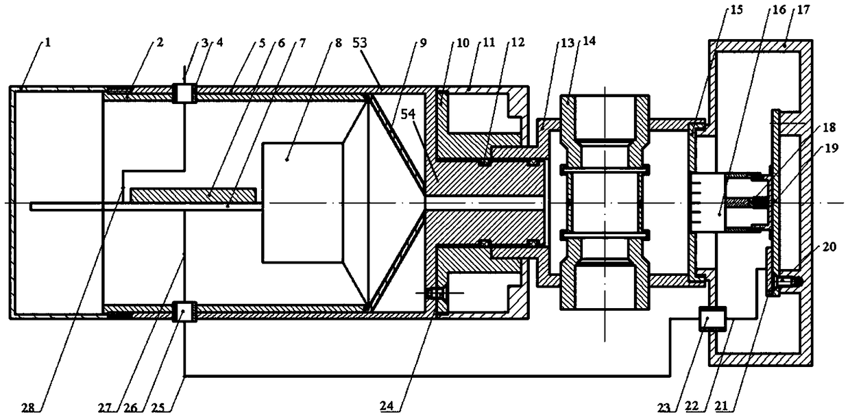
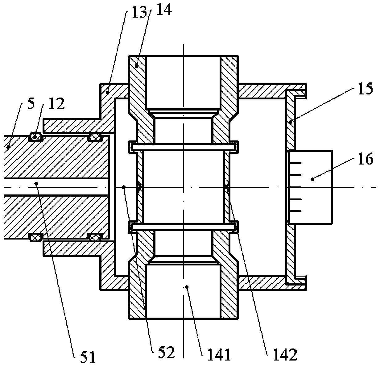
[0027] refer to figure 1 As shown, it is a schematic structural diagram of a sound intensity measurement and calibration device according to an embodiment of the present invention. The sound intensity measuring and calibrating device shown includes: a housing upper cover 1 , a housing 5 , a sleeve 2 , a circuit board 7 , a speaker 8 , a coupling cavity 13 , a coupling element 14 , a coupling cavity bottom cover 15 , and a reference microphone 16 . The shell 5 is divided into an upper end 53 and a lower end 54, and the inner diameter of the lower end 54 is smaller than the inner diameter of the upper end 53, and a sound transmission channel 51 is formed inside the lower end 54; The outer surface is closely matched, and th...


PUM


Abstract

The invention discloses a device and a method for measuring and calibrating the sound intensity. The device for measuring and calibrating the sound intensity comprises a shell upper cover, a shell, a sleeve, a circuit board, a loudspeaker, a coupling cavity, a coupling element, a coupling cavity bottom cover, and a reference microphone. The device for measuring and calibrating the sound intensity acquires a calibration signal generated by an external device and can be applied in various types of sound intensity measuring and calibrating environments and methods. Meanwhile, through the conduction of the sleeve and the conduction of the shell, a stable and effective sound source is obtained in the coupling cavity. Meanwhile, based on the coupling element of a symmetrical structure, a reference signal and a measurement signal, that are completely consistent with each other, can be obtained. Through comparing a reference signal fed back from the reference microphone and the above signal of the circuit, the calibration signal is more stable and more accurate. At the same time, the device for measuring and calibrating the sound intensity is highly integrated, convenient to carry about and immediate in detection.

Description

technical field [0001] The invention relates to the technical field of acoustic measurement, in particular to a sound intensity measurement and calibration device and method. Background technique [0002] Sound intensity refers to the average energy flux density of sound waves, and is an important technical indicator for measuring sound wave signals. Therefore, the measurement of sound intensity is of great significance. The sound intensity can be measured in any sound field, and the steady-state background noise has no effect on the sound power of the device under test when measuring the sound intensity. At present, there are two methods for measuring sound intensity: P-U method and P-P method. The P-U method refers to the measurement of the vibration velocity of a particle at a certain point in the sound field and the sound pressure at that point, and uses the product of the two to obtain the sound intensity of the measurement point; the P-P method refers to the measureme...

Claims


Application Information

Patent Timeline
Patent Type & Authority Patents(China)
IPC IPC(8): G01H17/00
CPCG01H17/00
Inventor 傅亮夏博雯贺才春杨涛
Owner ZHUZHOU TIMES NEW MATERIALS TECH
Why Eureka
Try Eureka