Modulation method for suppressing leakage current of two-H-bridge cascaded inverter

A technology of cascading inverters and modulation methods is applied in the direction of irreversible DC power input conversion to AC power output, AC power input conversion to DC power output, photovoltaic power generation, etc., which can solve the problem of low frequency of main harmonics of leakage current. , increase the volume, weight and cost of the inverter, and be affected by environmental factors, so as to reduce system loss and electromagnetic interference, improve the quality of grid current, and achieve the effect of simple implementation.

Active Publication Date: 2016-03-30
HEFEI UNIV OF TECH
View PDF5 Cites 19 Cited by
  • Summary
  • Abstract
  • Description
  • Claims
  • Application Information

AI Technical Summary

Problems solved by technology

[0005] 1) Passive filters are mainly composed of inductors and capacitors, which will increase the volume, weight and cost of the inverter and reduce the power conversion efficiency of the inverter when used in the circuit;
[0006] 2) The leakage current harmonic range is wide, and it is affected by environmental factors, which makes the filter parameter design process more complicated;
[0007] 3) The actual operating frequency of the cascaded H-bridge inverter is low, and the main harmonic frequency of its leakage current is also low, which leads to the unsatisfactory suppression effect of the leakage current of the filter
[0009] 1) This modulation method cannot suppress the leakage current flowing into the grid, and cannot improve the quality of grid-connected current;
[0010] 2) This method uses two in-phase stacked carriers, but the carrier needs to be phase-shifted by 180° every half power frequency cycle, which undoubtedly increases the difficulty of hardware implementation
[0011] It can be seen that the existing technology cannot better solve the leakage current problem of bridge cascaded H-bridge inverters without increasing additional costs and without affecting the quality of grid-connected current.

Method used


Image

  • Modulation method for suppressing leakage current of two-H-bridge cascaded inverter
  • Modulation method for suppressing leakage current of two-H-bridge cascaded inverter
  • Modulation method for suppressing leakage current of two-H-bridge cascaded inverter

Examples


Embodiment 1

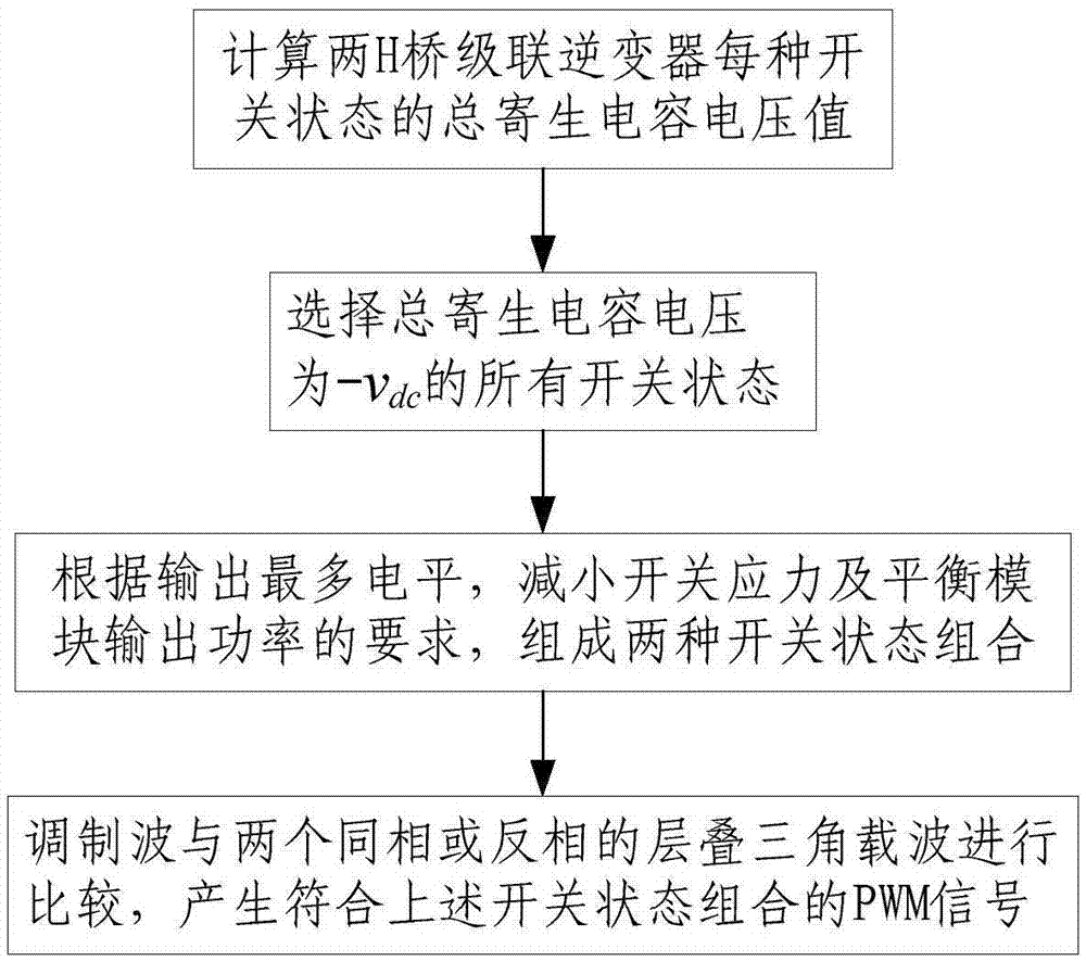
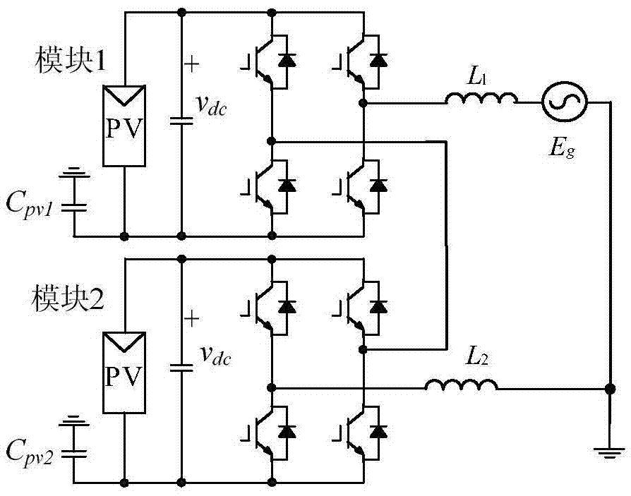
[0089] Step 1, set the DC voltage of the two modules of the two H-bridge cascaded inverters to be the same, and record it as v dc , to calculate all 16 switching states (S a1 \S b1 \S a2 \S b2 ) output voltage U O , module 1 parasitic capacitance voltage v N1O , module 2 parasitic capacitance voltage v N2O and the total parasitic capacitance voltage v NtO value,

[0090] u O =v dc (S a1 -S b1 +S a2 -S b2 ),

[0091] v N1O =-0.5v dc (S a1 +S b1 -S a2 +S b2 ),

[0092] v N2O =-0.5v dc (S a1 -S b1 +S a2 +S b2 ),

[0093] v NtO =v N1O +v N2O ;

[0094] Among them, S a1 is the switching function of the bridge arm connected to the total output terminal in module 1, S b1 is the switching function of the bridge arm connected to module 2 in module 1, S a2 is the switching function of the bridge arm connected to module 1 in module 2, S b2 is the switching function of the bridge arm connected to the total output terminal in module 2 and satisfies:

[0...

Embodiment 2

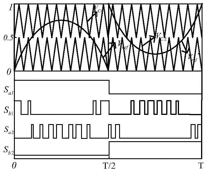
[0111] In this embodiment, the first switch combination in Embodiment 1 is implemented by comparing the modulated wave with two stacked triangular carrier waves with opposite phases. Realize the schematic diagram as Figure 4 as shown, Figure 4 Where T is the modulation wave period, and the carrier comparison method is the same as that in Embodiment 1. It can be seen that all the switch states generated by this comparison method are exactly the same as the first switch state combination.

Embodiment 3

[0113] In this embodiment, the second switch combination in Embodiment 1 is realized by comparing the modulated wave with two stacked triangular carrier waves of the same phase. The comparison method is as follows:

[0114] (1) When the modulation wave V ref is in the positive half cycle, that is, V ref ≥0, then S a1 = 1, S b2 = 0; S b1 By modulating wave and carrier V c1 Comparing to get, if V ref >V c1 , S b1 = 0, otherwise S b1 = 1; S a2 By modulating wave and carrier V c2 Comparing to get, if V ref >V c2 , S a2 = 1, otherwise S a2 = 0;

[0115] (2) When the modulation wave V ref is in the negative half cycle, that is, V ref a1 = 0, S b2 =1; In order to compare the carrier wave with the modulating wave, add 1 to the modulating wave to obtain the modified modulating wave V ref * , namely V ref * =V ref +1;S b1 by the modulation wave V ref * with carrier V c1 Comparing to get, if V ref * >V c1 , S b1 = 0, otherwise S b1 = 1; S a2 by the modulat...


PUM


Abstract

The invention discloses a modulation method for suppressing leakage current of a two-H-bridge cascaded inverter. The method comprises the following steps of calculating total parasitic capacitor voltage v<Nto> value of the two-H-bridge cascaded inverter at each switch-on state; selecting all switch-on states when the total parasitic capacitor voltage v<Nto) is -v<dc>; forming a combination of two switch-on states according to requirements of maximum level output, switch stress reduction and output power balance of a module; and comparing a modulation wave with a triangle carrier wave which is laminated by two same or opposite phases, and generating pulse width modulation (PWM) signals conforming to the above switch-on state combination, and allocating the PWM signals to corresponding pins. By the scheme, extra hardware cost is not needed, leakage current flowing into a power grid can be eliminated, and meanwhile, the leakage current of a single module is suppressed; and the method only requires two carrier waves to compare, the computation of a processor is reduced, and the implementation mode is simple.

Description

technical field [0001] The invention relates to a modulation method of a single-phase two H-bridge cascaded inverter, especially a modulation method capable of suppressing the leakage current of a non-isolated two H-bridge cascaded grid-connected photovoltaic inverter; it is suitable for photovoltaic grid-connected power generation field. Background technique [0002] In order to ensure the safety of use, the VDE4105 standard has strict restrictions on the common mode current (leakage current) of photovoltaic (Photovoltaic, PV) grid-connected systems. The power frequency isolation transformer on the grid side can realize electrical isolation between PV and power grid, and suppress leakage current. However, power frequency transformers are large in size, heavy in weight, high in cost, and low in system efficiency. If a high-frequency transformer is used to realize the electrical isolation of PV and grid, the system volume, weight and cost can be reduced, but the power conver...

Claims


Application Information

Patent Timeline
Patent Type & Authority Applications(China)
IPC IPC(8): H02M7/48H02M1/12H02J3/38
CPCH02J3/383H02M1/12H02M7/48H02M7/493H02M1/0038H02M1/007H02M1/123Y02E10/56
Inventor 王付胜于世能张兴
Owner HEFEI UNIV OF TECH
Why Eureka
Try Eureka