Rain sewage diverting and guiding system of valley-type waste landfill and using method thereof
A landfill, rain and sewage diversion technology, applied in the waterway system, sewer system, sewage discharge, etc., can solve the problems of incomplete rain and sewage diversion, increased leachate discharge, etc., to increase the sewage treatment capacity , reduce the load and prolong the service life
- Summary
- Abstract
- Description
- Claims
- Application Information
AI Technical Summary
Problems solved by technology
Method used
Image
Examples
Embodiment 1
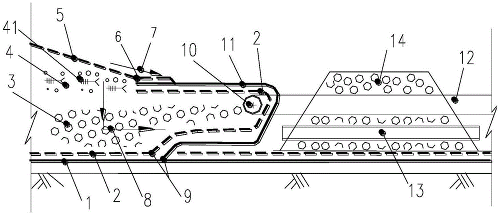
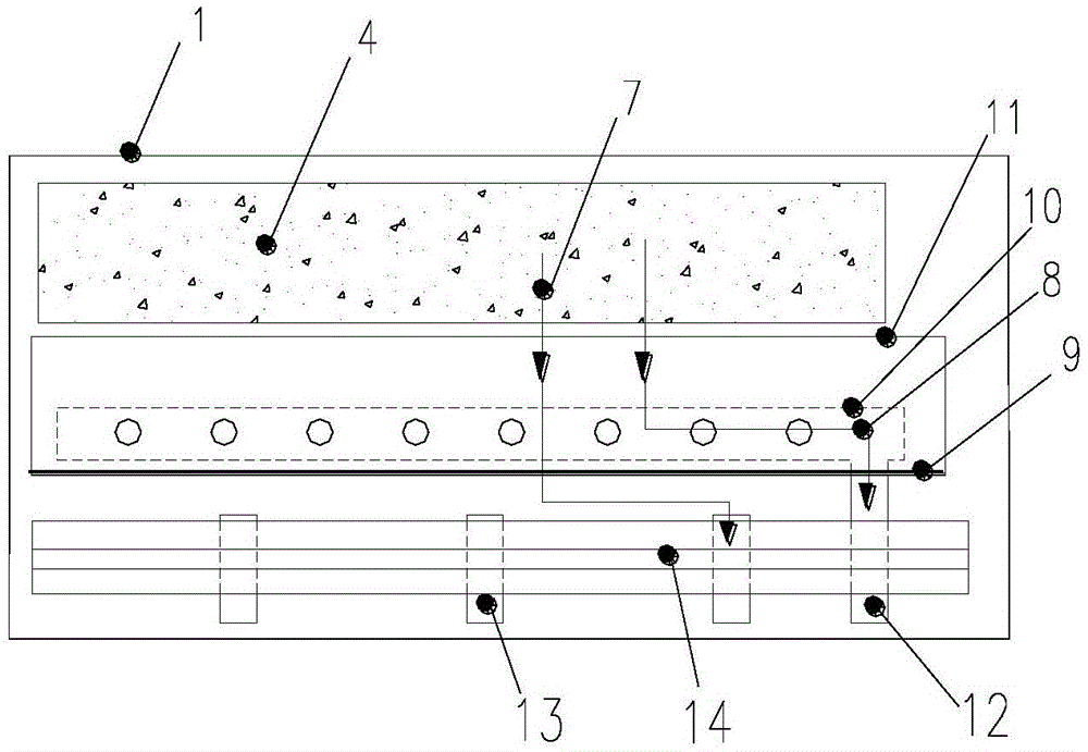
[0046] combine figure 1 and figure 2 , a rain and sewage diversion and diversion system for a valley-type garbage landfill, which includes a partition dam 14, a sewage pipe, a rainwater collection pipe 13, a geotechnical composite drainage network 2 and a non-woven geotextile 5, wherein the landfill area 4 From bottom to top, there are 2.0mm thick HDPE double-rough film I1, geotechnical composite drainage network 2 with high-density polyethylene as the main raw material, gravel layer 3, landfill layer 41 and 600g / m 2 The non-woven geotextile 5, wherein, the geotechnical composite drainage net 2 extends from the bottom of the landfill area 4 wrapped with the crushed stone layer 3 to the bottom of the slope foot 6 of the landfill area, and the outer side of the geotechnical composite drainage net 2 is provided with a layer of double Rough film 1.0mm thick HDPEII11, double rough film II11 extends from double rough film I1 at the bottom of landfill area 4 to the bottom of slope ...
Embodiment 2
[0068] Such as figure 1 As shown, a partition dam 14 is set up at the downstream of the slope foot of the landfill area 4, the inner diameter of the sewage collection flower pipe 10 is 150mm, and the material is HDPE, and the sewage collection flower pipe 10 in the landfill area 4 is laid in parallel with the partition dam 14, Cut the high-density polyethylene geotechnical composite drainage network 2 laid on the base of the landfill area 4, cut along the direction of the landfill operation area, and weld the new high-density polyethylene geotechnical composite drainage network 2 at the cut, Form a whole to ensure that the entire downstream of the landfill area can be fully covered by the geotechnical composite drainage network 2 . The 2.5mm thick HDPE double-rough mask I(1) and the 1.5mm thick HDPE double-rough mask II11 directly below the incision are welded to each other, and laid to 6 places at the slope foot of the landfill area, and the sewage collection flower tube 10 i...
Embodiment 3
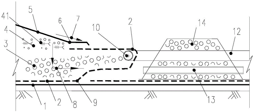
[0071] Such as image 3 As shown, the main function of the HDPE double-rough mask is to prevent leachate leakage, but the price is relatively expensive. In the case of satisfying the use function, the amount of HDPE double-rough mask can be reduced. In this embodiment, the 1.5mm thick HDPE mask is removed. The use of the double-rough mask means that the double-rough mask II11 is removed, only the geotechnical composite drainage net 2 is welded at the incision, and the thickness of the geotechnical composite drainage net 2 is appropriately increased, and the other parts are the same as in embodiment 2.
PUM
 Abstract
Description
Claims
Application Information
 - R&D
- Intellectual Property
- Life Sciences
- Materials
- Tech Scout
- Unparalleled Data Quality
- Higher Quality Content
- 60% Fewer Hallucinations
Browse by: Latest US Patents, China's latest patents, Technical Efficacy Thesaurus, Application Domain, Technology Topic, Popular Technical Reports.
© 2025 PatSnap. All rights reserved.Legal|Privacy policy|Modern Slavery Act Transparency Statement|Sitemap|About US| Contact US: help@patsnap.com


