
Mark with focusing and slant correction function and aligning method

A tilt correction and marking technology, applied in optical mechanical equipment, photo-engraving process of pattern surface, optics, etc., can solve the problem of affecting measurement reproducibility, error, insufficient to achieve high-precision focusing and leveling, and achieve improved Measurement reproducibility, high-precision focusing and leveling effects

Active Publication Date: 2016-04-06
SHANGHAI MICRO ELECTRONICS EQUIP (GRP) CO LTD
View PDF6 Cites 5 Cited by
  • Summary
  • Abstract
  • Description
  • Claims
  • Application Information

AI Technical Summary

Problems solved by technology

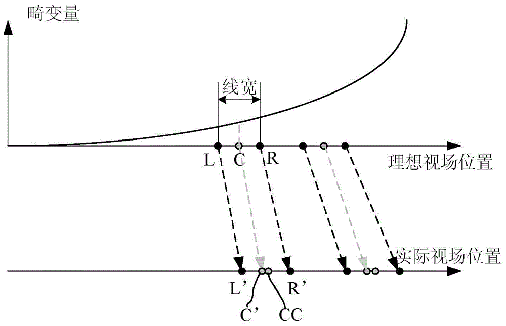
Its influence mechanism is that the nonlinear coupling between the position uncertainty of the measurement mark in the field of view and the distortion affects the measurement reproducibility, such as figure 2 shown
Although the FIA ​​system reduces the influence of distortion through multiple iterations so that the marker is always measured at a fixed position, the iterations consume a lot of time
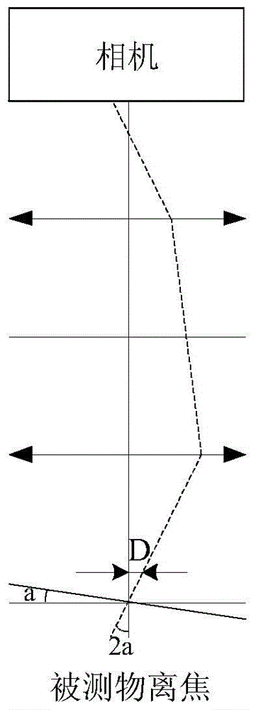
[0006] Secondly, if image 3 As shown, the defocusing tilt effect of the mark will also affect the measurement reproducibility, and the tilt angle a of the measured object will produce an error D
Although the focus and leveling system in the photolithography machine can realize the correction of tilt and defocus, because the focus and leveling measurement surface is the upper surface of the photoresist, and the alignment mark is sometimes located on the lower surface of the photoresist, the photoresist The thickness has certain fluctuations, so the focus and leveling system is not enough to achieve high-precision focus and leveling of the alignment marks
[0007] In addition, in the optical imaging system, although the automatic focusing technology has been widely used in the alignment sensor, the sensor that realizes the tilt correction while the automatic focusing has not been invented yet

Method used


Image

  • Mark with focusing and slant correction function and aligning method
  • Mark with focusing and slant correction function and aligning method
  • Mark with focusing and slant correction function and aligning method

Examples


Embodiment 1

[0053] like Figure 4As shown, Embodiment 1 of the present invention provides a mark with a focus adjustment and tilt correction design, the mark includes an alignment mark 20 and at least one pair of focus adjustment marks, and the focus adjustment mark is a square type focus mark or a grating type Focusing marks, the grating-type focusing marks are horizontal grating-type focusing marks or vertical grating-type focusing marks, and the focusing marks include a pair of square-type focusing marks, a pair of horizontal grating-type Focus marks and a pair of vertical grating-type focus marks, the focus marks include square-type focus marks 10, square-type focus marks 30, horizontal grating-type focus marks 11, horizontal grating-type focus marks 31. The vertical grating-type focusing mark 12 and the vertical grating-type focusing mark 32 . Among them, the square-shaped focusing mark 10 and the square-shaped focusing mark 30 are a pair of square-shaped focusing marks, and the hor...

Embodiment 2

[0100] Different from Embodiment 1, in Embodiment 2, the center of the alignment mark is not necessarily located at the midpoint of any pair of focusing marks, but only the distance to the two focusing marks is known. The best focus plane position of the alignment mark is obtained by using the known distance from the alignment mark to the two focusing marks. Compared with the first embodiment, the second embodiment provides a mark with less restrictive conditions, which meets the diverse needs of users.

[0101] In Embodiment 2, except for the above content, the marking and alignment methods are consistent with Embodiment 1, so details will not be repeated here.

Embodiment 3

[0103] Different from the first embodiment, in the third embodiment, the alignment mark is a horizontal line mark or a vertical line mark, which is used to measure the position in one direction. Compared with Embodiment 1, Embodiment 3 provides a marker for measuring a position in one direction, which meets the diverse needs of users.

[0104] In the third embodiment, except for the above content, the marking and alignment methods are the same as those in the first embodiment, so no more details are given here.


PUM


Abstract

The invention discloses a mark with a focusing and slant correction function and an aligning method. The mark comprises an aligning mark and at least one pair of focusing marks, wherein the center of the aligning mark is positioned on the middle point of a connecting line of any pair of the focusing marks; the focusing marks of any pair are arranged on two sides of the aligning mark in a manner of central symmetry; the aligning mark is a crossed mark or a star-shaped mark; the focusing marks are square type focusing marks or grating type focusing marks; the line width of the aligning mark is greater than discretization granularity; and the line width of the aligning mark is greater than twice of PSF width. The invention also provides the aligning method applied to the mark, and high-precision focusing leveling of the aligning mark is realized. Compared with the prior art, according to the mark provided by the invention, the influence of inclination on the mark is eliminated during focusing, so that the measurement reproducibility is improved; and moreover, the influence mechanism of distortion on the measurement reproducibility is analyzed, limited conditions for mark width are given out, and the measurement reproducibility is further improved.

Description

technical field [0001] The present invention relates to a mark with focus adjustment and tilt correction design and an alignment method, in particular to a mark comprising an alignment mark and at least one pair of focus adjustment marks and an alignment method thereof. Background technique [0002] In the integrated circuit manufacturing process, a complete chip usually requires multiple photolithography exposures to complete. Except for the first layer of lithography, the other layers of lithography must be accurately positioned before exposure to the graphics of this level and the graphics (ie marks) left by the exposure of the previous level, so as to ensure that there is a correct relationship between the graphics of each layer. The relative position, that is, the overlay accuracy. [0003] In the prior art, an alignment system based on the principle of optical imaging is one of the commonly used systems in lithography machines, such as NikonFIA system, UltratecMVS and...

Claims


Application Information

Patent Timeline
IPC IPC(8): G03F7/207G03F9/00
CPCG03F9/00G03F7/70683G03F9/7003G03F9/708
Inventor 杜荣陈跃飞
Owner SHANGHAI MICRO ELECTRONICS EQUIP (GRP) CO LTD
Learn More