

Negative Charge Pump Feedback Circuit
A technology of feedback circuit and charge pump, which is applied in the direction of adjusting electrical variables, control/regulation systems, instruments, etc., can solve the problems of occupation, large area, etc., and achieve the effect of reducing current, reducing area, and realizing output
- Summary
- Abstract
- Description
- Claims
- Application Information
AI Technical Summary
Problems solved by technology
Method used
Image

Examples
Embodiment Construction
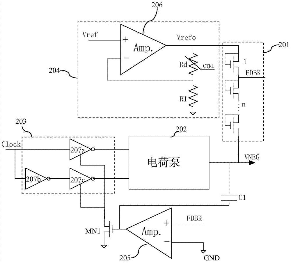
[0028] Such as figure 2 As shown, it is a schematic diagram of the negative pressure VNEG charge pump 202 feedback circuit of the embodiment of the present invention. The negative pressure VNEG charge pump 202 feedback circuit of the embodiment of the present invention includes:
[0029] The voltage divider circuit 201 is formed by connecting a plurality of MOS transistors in series, and the drains and gates of each of the MOS transistors are connected together. The voltage divider circuit 201 is connected to the negative voltage VNEG output by the charge pump 202 and the first reference voltage Vrefo Meanwhile, the voltage dividing circuit 201 outputs the divided voltage of the negative voltage VNEG and the first reference voltage Vrefo as the feedback voltage FDBK.
[0030] The first operational amplifier 205, the feedback voltage FDBK is connected to the first input terminal of the first operational amplifier 205, the second input terminal of the first operational amplifie...
PUM
 Abstract
Description
Claims
Application Information