
Rotating anode CT bulb with elastic metal fiber and graphene enhanced heat dissipation

A technology of rotating anode and elastic metal, which is applied in the direction of X-ray tube electrodes, X-ray tube parts, X-ray tube shell/container, etc. Heat away and other issues, to achieve high reliability, good air tightness, increase the effect of the connection area

Active Publication Date: 2017-11-21
电科睿视技术(北京)有限公司
View PDF4 Cites 0 Cited by
  • Summary
  • Abstract
  • Description
  • Claims
  • Application Information

AI Technical Summary

Problems solved by technology

[0003] At present, the shell sealing of CT bulbs is usually made of metal-glass sealing. Glass is used as the insulating part of the electrode, which has the characteristics of easy processing and molding, but it is easy to burst.
[0004] In addition, medical CT tubes generate X-rays when they are working, and the high-speed electron beam reaches the metal target, generating a lot of heat, and the metal target is easily broken down and melted.
In order to avoid breakdown and melting of the target, a high-speed rotating metal target is used. The rotating metal target is connected to the shell through a rolling bearing, and the inside of the bearing is in a vacuum state; The contact surface of the inner and outer rings conducts a small amount of conduction heat dissipation. This heat dissipation method is inefficient and cannot take away the heat generated by the metal target in time, thus affecting the service life of the CT tube.

Method used


Image

  • Rotating anode CT bulb with elastic metal fiber and graphene enhanced heat dissipation
  • Rotating anode CT bulb with elastic metal fiber and graphene enhanced heat dissipation

Examples


Embodiment 1

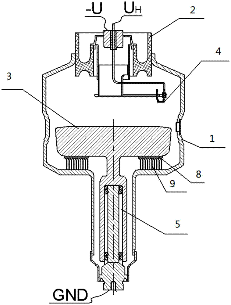
[0030] A rotating anode CT bulb that uses elastic metal fibers and graphene to enhance heat dissipation. The structural schematic diagram of the CT bulb is shown in figure 1 As shown, it mainly includes a tube shell, a rotating anode target 3 connected to the tube shell, and a cathode 4 located in the tube shell and corresponding to the position of the rotating anode target 3; wherein, the rotating anode target 3 passes through The bearing 5 is connected with the shell;

[0031] The casing includes a cathode ceramic section 2 and a metal section 1, wherein the cathode ceramic section 2 is a cylindrical structure with a central hole, mainly for insulation, and its two ends are respectively processed with annular grooves, which are located in the metal section 1 The groove depth of the annular groove at one end is smaller than the groove depth of the annular groove at one end outside the metal segment 1, and the end face inside the ring groove at one end outside the metal segmen...


PUM


Abstract

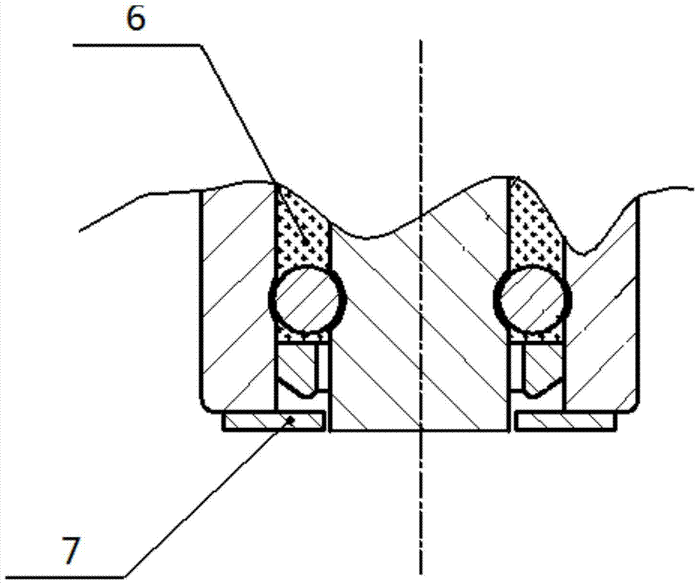
The invention discloses a rotating anode CT bulb tube employing elastic metal fibers and graphene for improving heat dissipation, and belongs to the field of vacuum electronic medical devices. The bulb tube mainly comprises a tube housing, a rotating anode target connected in the tube housing, and a cathode which is located in the tube housing and is opposite to the rotating anode target. The rotating anode target is connected with the tube housing through a bearing. The tube housing comprises a cathode ceramic segment and a metal segment. The cathode ceramic segment is in a cylindrical structure with a central hole, and two ends of the cathode ceramic segment are respectively provided with an annular groove. The depth of one annular groove at one end of the interior of the metal segment is less than the depth of the annular groove at one end of the exterior of the metal segment. Moreover, an inner end face of the annular groove at the end of the exterior of the metal segment is lower than an outer end face. Nano-level graphene powder is disposed in a bearing ball cavity, and two ends of the bearing ball cavity are provided with stopping pieces. The elastic metal fibers are disposed between the surface of the rotating anode target and the opposite surface of the tube housing, and contact with the tube housing and a target head.

Description

technical field [0001] The invention relates to a rotating anode CT bulb, which belongs to the field of vacuum electronic medical devices. Background technique [0002] CT machine is a disease detection instrument commonly used in hospitals. The CT machine has a high resolution ability, and the diagnostic effect is intuitive and accurate. CT tube, also known as X-ray tube, is the core component of CT machine, providing X-ray source for the whole CT equipment. Only when the CT tube provides stable and reliable X-rays, all functions of the CT machine can be realized. CT tube is mainly composed of shell, cathode, anode, bearing rotor, high voltage system and other parts. When the CT tube is working, the cathode filament is energized and heated, and electrons escape. The electrons are accelerated under the action of a strong electric field force, bombard the rotating target surface of the tube, and produce bremsstrahlung, thereby generating X-rays. [0003] At present, the sh...

Claims


Application Information

Patent Timeline
Patent Type & Authority Patents(China)
IPC IPC(8): H01J35/10H01J35/06H01J35/16
CPCH01J35/06H01J35/10H01J35/16
Inventor 盛兴王瑞海王宁红寇建勇
Owner 电科睿视技术(北京)有限公司
Learn More