Piston type pressure reducing valve

A piston-type, pressure-reducing valve technology, applied to valve details, safety valves, balance valves, etc., can solve problems such as large outlet pressure fluctuations, high water quality requirements, frequent diaphragm replacement, etc., to achieve small outlet pressure fluctuations, vibration Small, good flow effect

Inactive Publication Date: 2016-04-13
湘潭中基电站辅机制造有限公司
View PDF8 Cites 6 Cited by
  • Summary
  • Abstract
  • Description
  • Claims
  • Application Information

AI Technical Summary

Problems solved by technology

Since the pressure adjustment method is the water pressure difference between the upper and lower diaphragms, the response speed is slow, the outlet pressure fluctuates greatly, and the noise and vibration are large; the flow characteristics are poor, and when the inlet pressure and outlet flow change suddenly, it is easy to have a series pressure, that is, the outlet pressure is close to the inlet pressure; due to the structure Features, the decompression ratio is generally 2:1, the maximum is 3:1, the overall strength is not high, and the service life is short
The differential pressure diaphragm pressure reducing valve has no self-protection device, and a safety relief valve protection device must be equipped behind the valve; the applicable water quality requirements are high (requires no sediment impurities or very little content), the diaphragm is replaced frequently, and the stress point is thin. High failure rate

Method used


Image

  • Piston type pressure reducing valve

Examples


Embodiment Construction

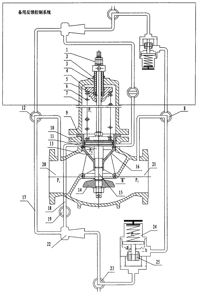
[0011] Such as figure 1 As shown, a piston pressure reducing valve includes a valve body 9 with an inlet and an outlet. The valve body 9 includes a valve cover 7, a main spring 6 located in the valve cover 7, a piston 11, and a piston rod 15. Its characteristics In that: the valve body 9 has two sets of symmetrical feedback control systems, the feedback control system includes a recoil blowdown structure; the center of the valve cover 7 is provided with a safety locking device, the upper part of the valve cover 7 is fixed with the spring seat 4, and the lower part is provided with a piston 11. A cylinder liner valve seat assembly 10 that is sealed with the piston 11 is provided around the piston 11; a main spring 6 that can push the piston 11 downward is provided between the piston 11 and the spring seat 4; The valve seat 16 fixedly connected to the valve cover 7 forms a pressure regulating chamber 13 between the valve seat 16 and the piston 11, and the pressure regulating cha...


PUM


Abstract

A piston type pressure reducing valve comprises a valve body with an inlet and an outlet. The valve body comprises a bonnet, a main spring, a piston and a piston rod, and the main spring is positioned in the bonnet. The piston type pressure reducing valve is characterized in that the valve body is provided with two symmetric feedback control systems, and each feedback control system comprises a backflushing blowdown structure; a safe locking device is arranged in the center of the bonnet, a spring seat is fixed on the upper part of the bonnet, and the piston is arranged on the lower part of the bonnet; the main spring capable of pushing the piston to move downwards is arranged between the piston and the spring seat; a valve seat fixedly connected with the bonnet is arranged under the piston; a pressure adjusting cavity is formed between the valve seat and the piston and is isolated from an inlet pressure cavity and an outlet pressure cavity; the piston rod is arranged in the center of the valve seat; the upper end of the piston rod is fixedly connected with the center of the piston; and a throttling cone is arranged at the lower end of the piston rod. The piston type pressure reducing valve provided by the invention is long in service life, high in adjustment sensitivity, good in outlet pressure characteristics, wide in pressure adjusting range, high in response speed, good in flow characteristics, small in noise vibration and high in water quality adaptive capacity.

Description

technical field [0001] The invention relates to the field of valves, in particular to a piston pressure reducing valve. Background technique [0002] The existing technology is generally imported differential pressure diaphragm pressure reducing valve. The differential pressure diaphragm type pressure reducing valve is composed of a main valve and a feedback system; the main valve is mainly composed of a diaphragm, valve stem, valve disc, guide claw, and the feedback system It is composed of a diaphragm control valve; when the system is working, the automatic adjustment of the feedback system control valve forms a differential pressure on the upper and lower sides of the diaphragm, so that the main valve disc forms an appropriate opening and stabilizes the outlet pressure. Since the pressure adjustment method is the water pressure difference between the upper and lower diaphragms, the response speed is slow, the outlet pressure fluctuates greatly, and the noise and vibration...

Claims


Application Information

Patent Timeline
IPC IPC(8): F16K17/22F16K31/12
Inventor 宋树基刘谦李冬初欧阳普照张剑军
Owner 湘潭中基电站辅机制造有限公司
Why Eureka
Try Eureka