Pulse transformer and manufacturing method thereof

A pulse transformer and winding technology, applied in magnetic bias transformers, fixed transformers or mutual inductances, transformer/inductor components, etc. Simple winding method, reducing short circuit and preventing poor withstand voltage

Active Publication Date: 2018-01-12
SHENZHEN SUNLORD ELECTRONICS
View PDF8 Cites 0 Cited by
  • Summary
  • Abstract
  • Description
  • Claims
  • Application Information

AI Technical Summary

Problems solved by technology

The new surface-mounted pulse transformer is manufactured by the automatic winding process. While realizing automation, it also has the characteristics of compact structure size and high coupling. However, due to the complicated winding method and the phenomenon of lead wire crossing when hanging the wire , the product has a high risk of poor withstand voltage characteristics

Method used


Image

  • Pulse transformer and manufacturing method thereof
  • Pulse transformer and manufacturing method thereof
  • Pulse transformer and manufacturing method thereof

Examples


Embodiment 1

[0069] A pulse transformer combined with PCB wiring

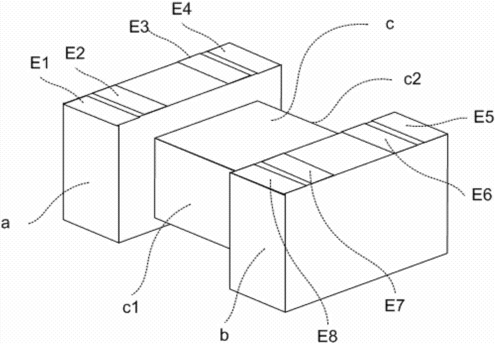
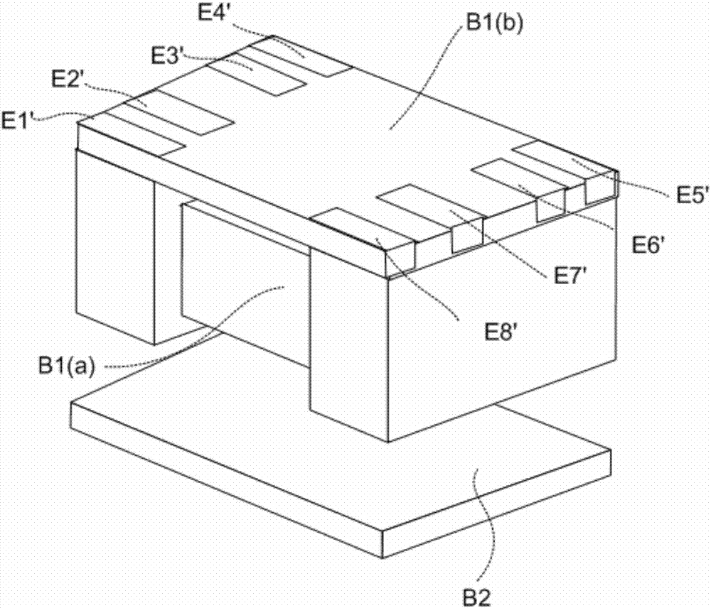
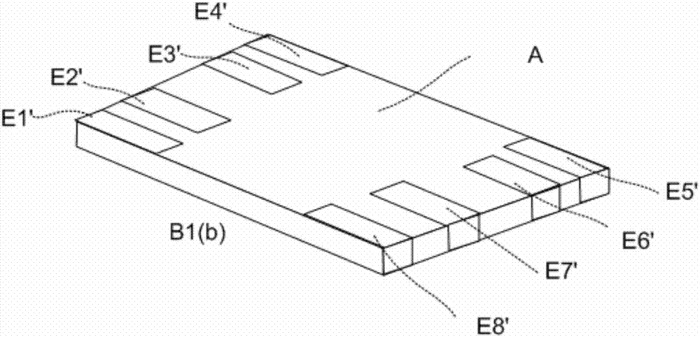
[0070] On the first magnetic core body B1, the starting end S1a and the ending S1b of the winding S1 are respectively connected to the first electrode E1 and the seventh electrode E7, and the starting end S2a and the ending S2b of the winding S2 are respectively connected to the second electrode E2 and the eighth electrode E8 The starting end S3a and the ending S3b of the winding wire S3 are connected to the third electrode E3 and the fifth electrode E5 respectively, and the starting end S4a and the ending S4b of the winding wire S4 are connected to the fourth electrode E4 and the sixth electrode E6 respectively.

[0071] Wherein, the winding wires S1 and S3 start to wind from the first side c1 of the central column c of the first magnetic core body B1 and end from the second side c2 of the central column c. The windings S2 and S4 start from the first side c1 of the central column c and end from the second side c2 of the ce...

Embodiment 2

[0088] A pulse transformer combined with PCB wiring

[0089] On the first magnetic core body, the starting end S1a and the ending S1b of the winding S1 are respectively connected to the first electrode E1 and the eighth electrode E8, and the starting end S2a and the ending S2b of the winding S2 are respectively connected to the second electrode E2 and the seventh electrode E7, The starting end S3a and the ending S3b of the winding wire S3 are connected to the third electrode E3 and the sixth electrode E6 respectively, and the starting end S4a and the ending S4b of the winding wire S4 are connected to the fourth electrode E4 and the fifth electrode E5 respectively.

[0090] The windings S1 and S3 start to be wound from the first side c1 of the central column c and end from the second side c2 of the central column c. The windings S2 and S4 start to be wound from the first side c1 of the central column c and end from the second side c2 of the central column c.

[0091] The windi...

Embodiment 3

[0110] A pulse transformer combined with PCB wiring

[0111] On the first magnetic core body, the starting end S1a and the ending S1b of the winding S1 are respectively connected to the first electrode E1 and the sixth electrode E6, and the starting end S2a and the ending S2b of the winding S2 are respectively connected to the second electrode E2 and the fifth electrode E5, The start S3a and end S3b of the winding S3 are respectively connected to the third electrode E3 and the eighth electrode E8, and the start S4a and end S4b of the winding S4 are respectively connected to the fourth electrode E4 and the seventh electrode E7.

[0112] The windings S1 and S2 start to be wound from the first side c1 of the central column c, and end from the second side c2 of the central column c. The windings S3 and S4 start from the second side c2 of the central column c and end from the first side c1 of the central column c.

[0113] The windings S1 and S2 are wound on the center column c al...


PUM


Abstract

A pulse transformer comprises a first core body, wherein the first core body is provided with a plurality of electrodes, multiple winding wires wind around the first core body and are connected with corresponding electrodes to form multiple windings, the multiple windings are in corresponding wiring connection with PCB (printed circuit board) welding plates, and accordingly, the characteristics of a transformer product are obtained due to combination with the PCB welding plates; one part of the multiple windings are connected with the corresponding PCB welding plates to form primary windings, and the other part of the multiple windings are connected with the corresponding PCB welding plates to form secondary windings. The invention further discloses a corresponding manufacturing method of the pulse transformer. The pulse transformer is simple to manufacture and has remarkable advantages of avoidance of lead crossing and prevention of poor voltage resistance.

Description

technical field [0001] The invention relates to a pulse transformer and a manufacturing method thereof, in particular to a surface-mounted pulse transformer which adopts PCB (Printed Circuit Board) wiring to realize functions. Background technique [0002] With the increasing network coverage, a wave of terminal equipment innovation led by Internet technology has gradually set off. Pulse transformer, also known as network isolation transformer, or data mercury, as a key component of network interface, is widely used in network switches, routers, network cards, hubs and other equipment. Between the transceiver chip and the network interface, the pulse transformer mainly plays the role of signal coupling, high voltage isolation, impedance matching, and electromagnetic interference suppression. [0003] At present, traditional pulse transformers have the characteristics of low magnetic flux leakage, high coupling, and high signal bandwidth. However, because traditional pulse t...

Claims


Application Information

Patent Timeline
Patent Type & Authority Patents(China)
IPC IPC(8): H01F19/08H01F27/28H01F27/30H01F27/29
CPCH01F19/08H01F27/2828H01F27/292H01F27/306H01F2019/085
Inventor 刘金南黄敬新陈苗
Owner SHENZHEN SUNLORD ELECTRONICS
Why Eureka
Try Eureka