Oil-immersion-type testing transformer with cooling circulation structure

A technology for testing transformers and cooling cycles. It is applied to transformers, transformer/inductor cooling, and transformer/inductor components. It can solve the problems of small heat exchange area, inability to cool the internal temperature, and inability to achieve heat dissipation and cooling effects. Achieve the effects of increasing the contact area, good safety performance, and improving the cooling and heat dissipation effect

Active Publication Date: 2016-04-13
JIANGSU SHENGHUA ELECTRIC
View PDF7 Cites 1 Cited by
  • Summary
  • Abstract
  • Description
  • Claims
  • Application Information

AI Technical Summary

Problems solved by technology

The water cooling method is one of the more common cooling methods for transformers on the market at present, that is, a water cooling device is installed on the transformer. This method is generally realized by the water circulation outside the primary or secondary hollow wire tube surrounded by the iron core. The water cooling device is placed outside the coil. This local cooling method can only cool the surface temperature, but not the internal temperature. The heat exchange area between the cooling device and the coil is small, which cannot achieve good heat dissipation and cooling effect.

Method used


Image

  • Oil-immersion-type testing transformer with cooling circulation structure
  • Oil-immersion-type testing transformer with cooling circulation structure
  • Oil-immersion-type testing transformer with cooling circulation structure

Examples


Embodiment Construction

[0022] Embodiments of the present invention will be further described in detail below in conjunction with the accompanying drawings.

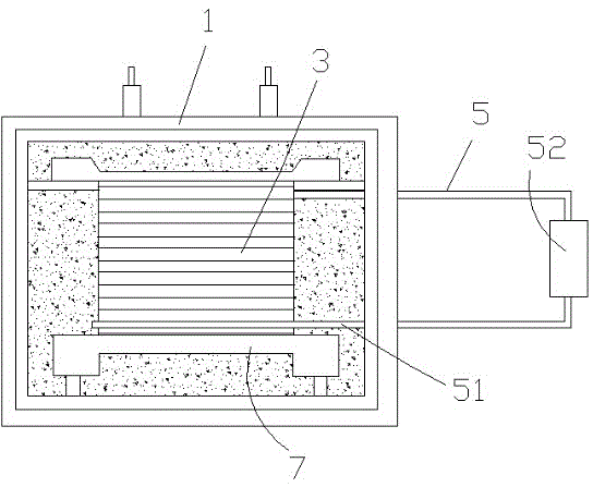
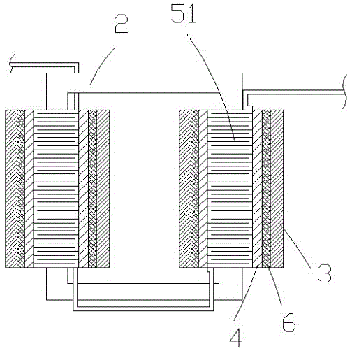
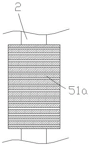
[0023] The oil-immersed test transformer with a cooling cycle structure of the present invention includes a test transformer shell 1 filled with insulating oil, and the test transformer shell 1 is provided with an iron core 2, a high-voltage coil 3 and a low-voltage coil 4 , the high-voltage coil 3 and the low-voltage coil 4 are coaxially arranged on the iron core 2, and the high-voltage coil 3 is located outside the low-voltage coil 4. It is characterized in that: the oil-immersed test transformer also includes a cooling cycle structure 5, and the cooling cycle structure 5 includes a cooling pipe 51 And the air compressor 52, the cooling pipe 51 is filled with tetrafluoroethane, the cooling pipe 51 is attached to the iron core 2 and circles around the iron core 2, the cooling pipe 51 separates the low-voltage coil 4 from the iron core 2, and th...


PUM


Abstract

The invention discloses an oil-immersion-type testing transformer with a cooling circulation structure. The oil-immersion-type testing transformer comprises a testing transformer shell. The testing transformer shell is filled with insulating oil. An iron core, a high-voltage coil and a low-voltage coil are arranged in the testing transformer shell, the high-voltage coil and the low-voltage coil are coaxially arranged on the iron core, and the high-voltage coil is located outside the low-voltage coil. The oil-immersion-type testing transformer is characterized by further comprising the cooling circulation structure; the cooling circulation structure comprises a cooling pipe and an air compressor, the cooling pipe is filled with tetrafluoroethane, attached to the iron core and wound around the iron core, the low-voltage coil is separated from the iron core through the cooling pipe, necks are formed in the outer side wall of the cooling pipe and matched with the low-voltage coil in shape, and the low-voltage coil can be embedded into the clamping grooves to enable the low-voltage coil and the cooling pipe to be integrally wound around the iron core. The oil-immersion-type testing transformer has the advantages of being good in cooling effect and novel in structure.

Description

technical field [0001] The invention belongs to the technical field of test transformers, and relates to a cooling device for a dry-type transformer, in particular to an oil-immersed test transformer with a cooling cycle structure. Background technique [0002] test transformer, referred to as AC withstand voltage test Provides high voltage transformers. It is characterized by high output voltage, small capacity, transformer Short circuit impedance It is very large and the ratio is very large. [0003] Since the test transformer needs to be used on the test site, it is necessary to design a compact structure to minimize the volume under the premise of meeting the test capacity, so as to facilitate transportation and on-site installation. For the test transformer, the coil generates a lot of heat when it works for a long time, and the coil is easy to burn out, resulting in damage to the test transformer. [0004] In order to ensure that the heat generated by the test tra...

Claims


Application Information

Patent Timeline
Patent Type & Authority Applications(China)
IPC IPC(8): H01F38/00H01F27/20H01F27/32H01F27/28G01R31/12
CPCG01R31/12H01F27/20H01F27/2871H01F27/2876H01F27/321H01F27/323H01F38/00
Inventor 黄天顺汤有华
Owner JIANGSU SHENGHUA ELECTRIC
Why Eureka
Try Eureka