Suppression method for neutral point voltage imbalance of five-level inverter

A neutral point voltage and inverter technology, applied in the direction of irreversible DC power input conversion to AC power output, electrical components, output power conversion devices, etc., can solve power supply short circuit, capacitor voltage imbalance, circuit cost increase and other issues, to achieve the overall efficiency improvement, simple control scheme, and reduce coupling effects

Active Publication Date: 2016-04-13
HENAN HAORUI ELECTRIC
View PDF3 Cites 10 Cited by
  • Summary
  • Abstract
  • Description
  • Claims
  • Application Information

AI Technical Summary

Problems solved by technology

A bridge arm uses multiple switching tubes in series. Although the overall pressure resistance requirement is met, due to the differences in the operating speed, parasitic capacitance, parasitic resistance, and parasitic capacitance of the switching device during the manufacturing process, there may be differences in each switching tube. The partial voltage on the inverter is different, the light one will affect the power quality of the inverter output, and the serious one will break down the switching tube of the entire inverter, causing a short circuit of the power supply, damaging the inverter itself and related electrical equipment, causing property loss and damage to the inverter. Personal safety
[0003] The most common problem in the prior art is that due to different loads and different switch states, some capacitors on the DC side are charging and some are discharging in a complete cycle, making the capacitor voltage unbalanced, which eventually leads to output level fluctuations. Unbalanced, resulting in unbalanced output voltage or output current of the three-phase inverter
Due to the unbalanced neutral voltage, the output voltage will not be piled up, and the harmonic content of the output power will be increased. During high-power transmission, the five-level inverter will degenerate into a three-level or two-level working state.
[0004] At present, there are many research methods on neutral point current offset, but all of them are relatively simple. Generally, the capacitive current is controlled according to the magnitude and direction of the DC side capacitive current offset, but this method is slow and to a certain extent Affect the power output quality
Another method adopts a chopper circuit, but its circuit structure is complicated and the cost of the whole circuit increases
There are also some methods that use software to control the SVPWM voltage space vector of the inverter switch tube to achieve the balance of the DC side voltage, but whether it is to detect the direction of the output power of the inverter, the direction of the output current or the value of the instantaneous current, When the output power of the inverter is relatively small, the effect of adjusting the voltage imbalance on the DC side by adjusting the output pulse is poor, and the voltage balance on the DC side cannot be achieved.
Others, such as using a switch clamp circuit as a measure to suppress the neutral point voltage offset, a simple clamp circuit often controls the voltage around a certain value, and when the DC side voltage fluctuates, the clamp circuit cannot be based on the DC voltage. The fluctuation of the side voltage value makes a dynamic adjustment to the limit value of the limit circuit voltage, which still limits the capacitor voltage to the original value, so its dynamic response cannot meet the requirements.

Method used


Image

  • Suppression method for neutral point voltage imbalance of five-level inverter

Examples


Embodiment 1

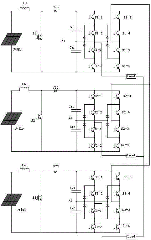
[0021] Such as figure 1As shown, the suppression method in the A phase is: when the capacitors CA1 and CA2 are in different working states, the voltages at both ends of CA1 and CA2 will be different, thus causing the voltage at point A1 to be not 1 / 2 of the DC side Voltage, causing the neutral point potential of the inverter output voltage to be non-zero, ensuring that the voltage at point A1 is maintained at 1 / 2 of the DC side voltage is the main measure to eliminate the neutral point potential shift of the output voltage, as follows:

[0022] When working in the positive half cycle, when the voltage across the capacitor CA1 is higher than the voltage across the capacitor CA2 at a certain moment, the switching tubes S1-1, S1-2, S1-4 and -3 is turned on, because the capacitor CA1 is connected to the load, and the voltage at both ends of the circuit will decrease, and at the same time, the capacitor CA2 will be charged, and the voltage on it will increase until the voltage at ...

Embodiment 2

[0025] Such as figure 1 As shown, the suppression method in the B phase is: when the capacitors CB1 and CB2 are in different working states, the voltages at both ends of CB1 and CB2 will be different, thus causing the voltage at point B1 to be not 1 / 2 of the DC side Voltage, causing the neutral point potential of the inverter output voltage to be non-zero, ensuring that the voltage at point B1 is maintained at 1 / 2 of the DC side voltage is the main measure to eliminate the neutral point potential shift of the output voltage, as follows:

[0026] When working in the positive half cycle, when the voltage across the capacitor CB1 is higher than the voltage across the capacitor CB2 at a certain moment, the switching tubes S2-1, S2-2, S2-4 and -3 is turned on, because the capacitor CB1 is connected to the load, and the voltage at both ends of the circuit will decrease, and the capacitor CB2 will charge at the same time, and the voltage on it will increase until the voltage at both...

Embodiment 3

[0029] Such as figure 1 As shown, the suppression method in the C phase is: when the capacitors CC1 and CC2 are in different working states, the voltages at both ends of CC1 and CC2 will be different, thus causing the voltage at C1 to be not 1 / 2 of the DC side Voltage, causing the neutral point potential of the inverter output voltage to be non-zero, ensuring that the voltage at point C1 is maintained at 1 / 2 of the DC side voltage is the main measure to eliminate the neutral point potential shift of the output voltage, as follows:

[0030] When working in the positive half cycle, when the voltage across the capacitor CC1 is higher than the voltage across the capacitor CC2 at a certain moment, the switching tubes S3-1, S3-2, S3-4 and -3 is turned on, because the capacitor CC1 is connected to the load, and the voltage at both ends of the circuit will decrease, and the capacitor CC2 will charge at the same time, and the voltage on it will increase until the voltage at both ends ...


PUM


Abstract

The invention discloses a suppression method for a neutral point voltage imbalance of a five-level inverter. Capacitors are connected with a load by detecting, comparing and judging voltage amplitudes on the capacitors at a direct current side and controlling switch tubes to be connected or disconnected; the capacitor with a high voltage is discharged; and charging control is carried out on the capacitor with a low voltage, so that parallel capacitors on each upper bridge arm and each lower bridge arm all can obtain a mean direct current side voltage; and the condition that neutral voltages constantly are 1/2 of the direct current side voltage is ensured. Vector synthesis of an original SVPWM is adjusted; and meanwhile, three independent circuits are adopted by a three-phase inverter. The deviation of the neutral point voltages is within +/-10V; the adjusting time is within 0.1s; THD of a current output by the inverter does not exceed 3%; the direct current side voltage of the inverter is that voltage ripples on the capacitors CS1 and CS2 do not exceed 2%; and the overall efficiency of the inverter is improved by about 1-1.5.

Description

technical field [0001] The present invention mainly relates to the field of power electronics and new energy, and the specific description is to control the voltage offset of the neutral point of the five-level inverter used in the photovoltaic power generation system, and eliminate the neutral point offset that brings the inverter itself. Suppression method of neutral point voltage unbalance of adverse effects of five-level inverter. Background technique [0002] With the increasing tension of traditional energy sources, the application scale of photovoltaic power sources mainly based on solar energy is increasing, and the five-level inverter has greater power output, higher voltage level and better power output quality. occupy more market share. Since the withstand voltage of a single switching device is limited to a certain extent, only by connecting multiple switching devices to one bridge arm in series can the higher voltage requirements of the DC side of the inverter ...

Claims


Application Information

Patent Timeline
Patent Type & Authority Applications(China)
IPC IPC(8): H02M7/49H02M7/487
Inventor 高德义李少军郑会军甄龙涛马帅
Owner HENAN HAORUI ELECTRIC
Why Eureka
Try Eureka