Array type microplasma generating device based on conductive coating

A conductive coating, plasma technology, applied in the direction of plasma, electrical components, etc., can solve the problems of complex discharge structure design, uneven plasma, high discharge requirements, and achieve exquisite device structure, fully uniform propagation, and low discharge temperature. Effect

Inactive Publication Date: 2016-04-13
DALIAN NATIONALITIES UNIVERSITY
View PDF5 Cites 9 Cited by
  • Summary
  • Abstract
  • Description
  • Claims
  • Application Information

AI Technical Summary

Problems solved by technology

However, the existing array plasma discharge devices generally have problems such as uneven plasma generation, low efficiency, high discharge requirements, and complex discharge structure design, which cannot meet people's needs.
[0003] In summary, the existing array type plasma discharge device cannot meet the demand for large-area uniform plasma generation, and a new array type micro plasma discharge device is needed

Method used


Image

  • Array type microplasma generating device based on conductive coating
  • Array type microplasma generating device based on conductive coating
  • Array type microplasma generating device based on conductive coating

Examples


Embodiment 1

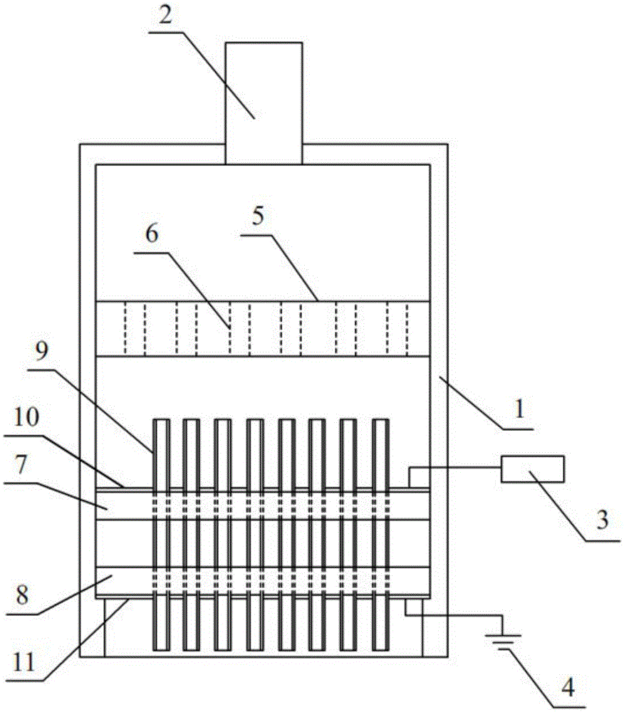
[0039] Conductive coatings A and B are made of graphite materials, which are respectively used as high-voltage electrodes and ground electrodes, and the thickness of conductive coatings A and B are both 300 microns.

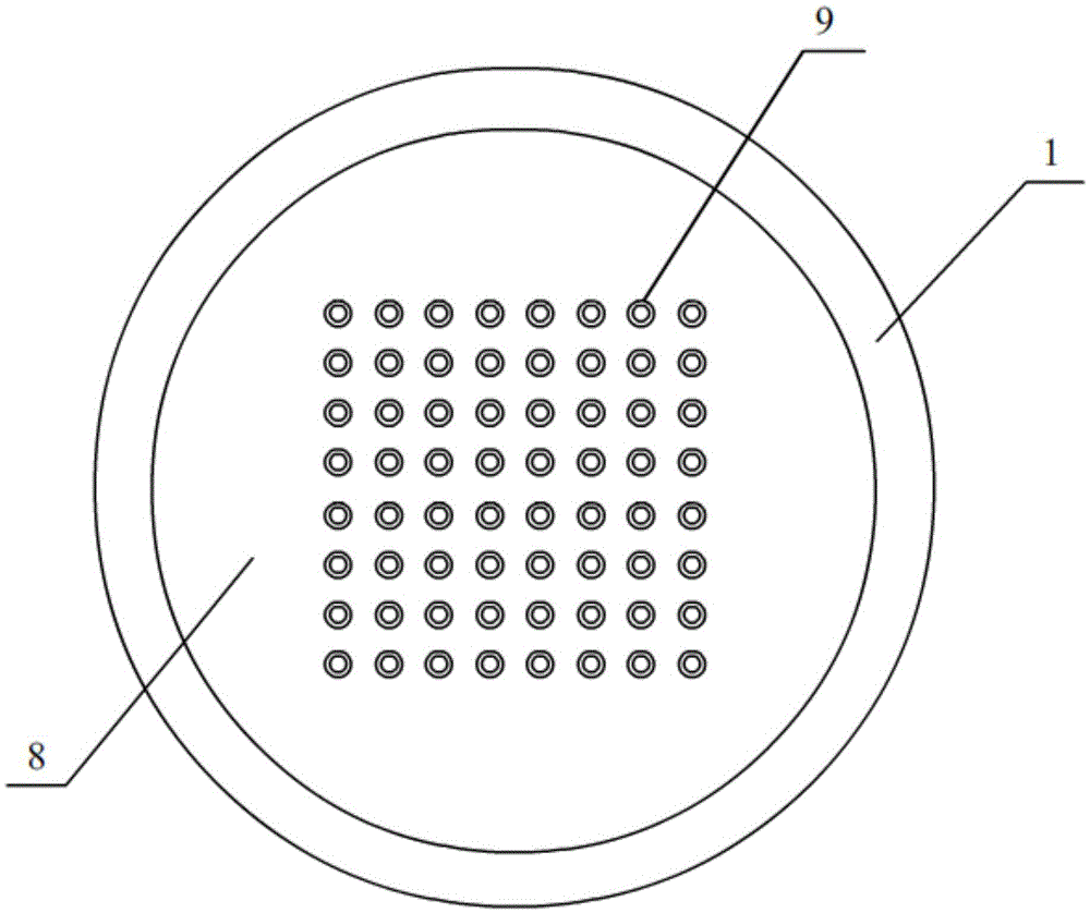
[0040] The insulating dielectric tube is made of quartz material, the length of the insulating dielectric tube is 20 mm, the inner diameter of the insulating dielectric tube is 100 microns, the outer diameter is 300 microns, and the thickness of the tube wall is 100 microns. The selected insulating medium tubes form an array form of 8*8 with a total of 64 pieces, and the distance between the tubes is 1mm.

[0041] Use plexiglass to make dielectric boards A and B, both of which have a length of 50 mm, a width of 50 mm, and a thickness of 5 mm.

[0042] Helium was selected as the discharge gas, and the gas flow rate was 2L / min.

[0043] The pulse power supply is selected as the power supply, the discharge voltage of the pulse power supply is 15kV, and the discharg...

Embodiment 2

[0047] Graphite is selected as the conductive coating A and B as the high-voltage electrode and the ground electrode respectively, and the thickness of the conductive coating is 500 microns.

[0048] The insulating medium tube is made of quartz material, the length of the insulating medium tube is 17 mm, the inner diameter of the insulating medium tube is 300 microns, the outer diameter is 500 microns, and the thickness of the tube wall is 100 microns. The selected insulating medium tubes form an array of 100 pieces in total of 10*10, and the distance between the tubes is 1.5mm.

[0049] Use plexiglass to make dielectric boards A and B, the length of dielectric boards A and B are both 80 mm, the width is 80 mm, and the thickness is 7 mm.

[0050] Air is selected as the discharge gas, and the gas flow rate is 3L / min.

[0051] The AC power is selected as the power source, the discharge voltage of the AC power is 10kV, and the discharge frequency is 8kHz.

[0052] During the st...


PUM


Abstract

An array type microplasma generating device based on a conductive coating comprises the components of an insulating housing, an inlet pipe, a high-voltage power supply and a ground electrode. The insulating housing has a cylindrical structure. One end of the insulating housing is closed, and the other end is open. The closed end of the insulating housing is communicated with the inlet pipe. The middle part of the insulating housing is provided with a circular flow sharing plate in radical direction. The flow sharing plate is provided with flow sharing holes which are arranged uniformly. A dielectric board A and a dielectric board B are mounted below the flow sharing plate, and furthermore a space is kept between the dielectric board A and the dielectric board B. The surfaces of the dielectric board A and the dielectric board B are provided with jacks which correspond with one another in the vertical direction. Insulating dielectric pipes are inserted and fixed between the jacks of the two dielectric boards, wherein the jacks correspond with one another in the vertical direction. Each insulating dielectric pipe has a pipe structure with an upper opening and a lower opening. The upper surface of the dielectric board A is provided with a conductive coating A which is connected with the high-voltage power supply through a lead. The lower surface of the dielectric board B is provided with a conductive coating B which is connected with the ground electrode through a lead. The array type microplasma generating device has advantages of high uniformity, concise structure, low cost, etc.

Description

technical field [0001] The invention relates to the field of plasma discharge, in particular to a plasma discharge device based on a conductive coating. Background technique [0002] At present, atmospheric pressure non-equilibrium plasma discharge has been a research hotspot in the field of disinfection and sterilization in biology, medicine and agriculture. Among them, the generation of large-area uniform plasma by array micro-plasma discharge has attracted extensive attention from experts and scholars around the world. It is known that the structure of the array micro-plasma discharge device and the stability of the discharge determine various factors such as the density of the generated plasma, the type of active species, and the concentration of the active species. However, the existing array plasma discharge devices generally have problems such as uneven plasma generation, low efficiency, high discharge requirements, and complex discharge structure design, which canno...

Claims


Application Information

Patent Timeline
Patent Type & Authority Applications(China)
IPC IPC(8): H05H1/24
CPCH05H1/2406H05H1/2425H05H1/2443H05H2245/36
Inventor 刘东平彭一峰夏洋徐博深齐志华
Owner DALIAN NATIONALITIES UNIVERSITY
Why Eureka
Try Eureka