Liquid dehumidification combined vortex tube low-temperature air-flow output device and pulverizing system

A liquid dehumidification and output device technology, applied in the field of low-temperature crushing, can solve the problems of large power consumption, waste of cooling capacity, complex system, etc., and achieve the effects of saving energy, saving energy consumption, and reducing specific heat capacity

Inactive Publication Date: 2016-04-20
ZHEJIANG UNIV
View PDF4 Cites 9 Cited by
  • Summary
  • Abstract
  • Description
  • Claims
  • Application Information

AI Technical Summary

Problems solved by technology

), but this treatment method is not only complicated in the system, but also causes a certain waste of cooling capacity
In addition, due to the limitation of the principle of the freeze-drying device, after passing through the freeze-drying machine, the temperature of the airflow can only be reduced to about 2°C, and an air cooling device needs to be added later to ensure a better effect of the subsequent impact crushing process, which in turn consumes A large amount of electric energy, resulting in a large waste

Method used


Image

  • Liquid dehumidification combined vortex tube low-temperature air-flow output device and pulverizing system
  • Liquid dehumidification combined vortex tube low-temperature air-flow output device and pulverizing system
  • Liquid dehumidification combined vortex tube low-temperature air-flow output device and pulverizing system

Examples


Embodiment Construction

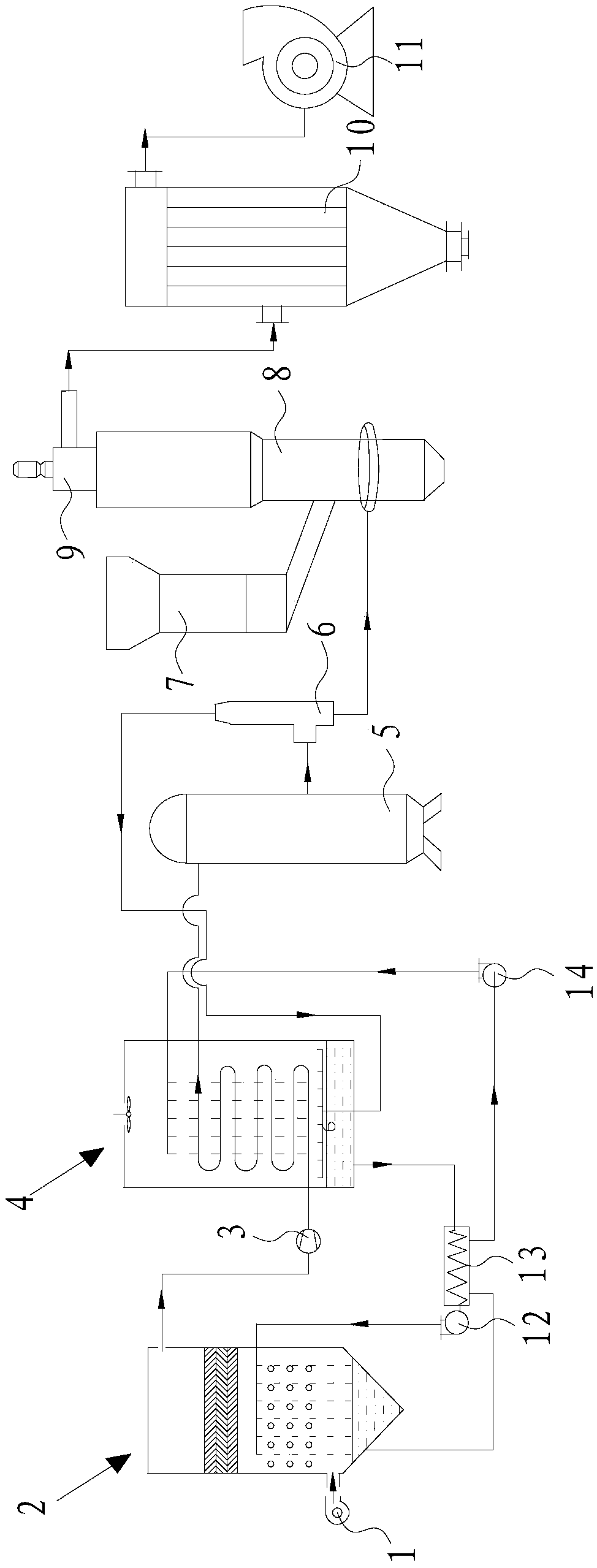
[0036] Such as figure 1 As shown, the low-temperature jet crushing system of the present embodiment includes: blower 1, drier 2, compressor 3, reducer 4, gas storage tank 5, vortex tube 6, freezer 7, fluidized bed 8, turbo separator 9. Pulse bag collector 10, induced draft fan 11, infusion pump 12, heat exchanger 13 and infusion pump 14.

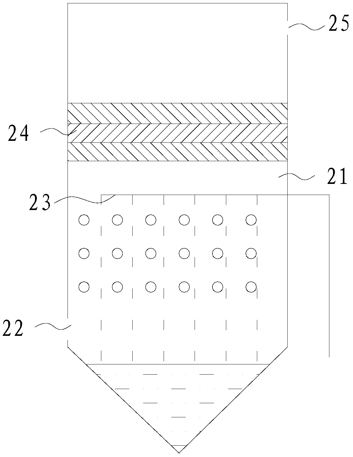
[0037] The dryer 2 includes a drying chamber 21, an air inlet 22, a first spraying unit 23, a defogging layer 24 and an air outlet 25, the air inlet 22 is arranged at the bottom of the drying chamber 21, and the first spraying unit 23 is arranged in the drying chamber 21 Inside and above the air inlet 22 , the air outlet 25 is arranged on the drying chamber 21 and above the first spraying unit 23 , and the demister layer 24 is arranged between the first spraying unit 23 and the air outlet 25 .

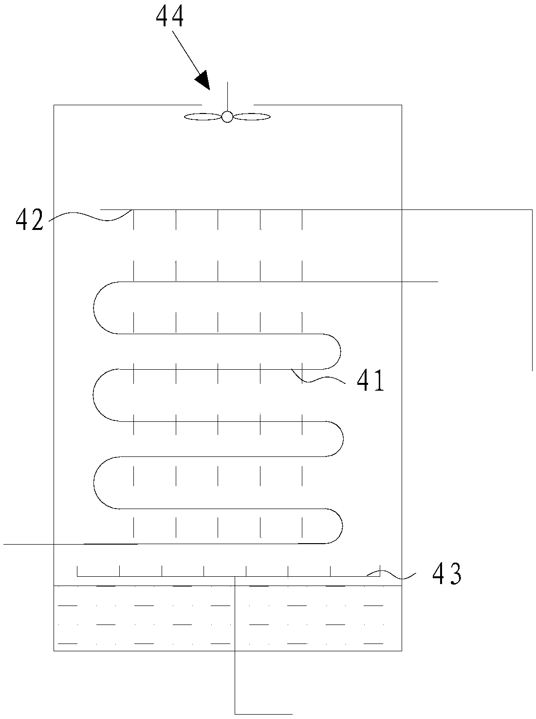
[0038] The reducer 4 is provided with a heat exchange coil 41 and a second spray unit 42 located above the heat exchange coil 41. The heat exchange...


PUM


Abstract

The invention discloses a liquid dehumidification combined vortex tube low-temperature air-flow output device, which comprises an air intake unit, a drier, a compressor, a reducer, an air storage tank and a vortex tube. The air intake unit conveys gas to be dried into the drier; the compressor compresses the dried gas from the drier; the reducer receives high temperature and high pressure gas from the compressor and gas from a hot end of the vortex tube which are used as heat sources; a liquid storage tank stores dried high pressure gas outputted from the reducer; the vortex tube carries out hydrocyclone separation on high pressure gas from the liquid storage tank; a cold end of the vortex tube outputs low temperature air-flow; and the reducer carries out evaporation and concentration on a dilute desiccant from the drier. The invention also discloses a liquid dehumidification combined vortex tube low-temperature air-flow pulverizing system. Low-grade heat energy self-produced by the system is used as a heat source for concentration reduction of the desiccant. No extra energy is consumed, and dried gas with high dryness is obtained. As low-temperature air-flow is outputted by the refrigeration effect of the vortex tube, energy utilization is more economical and reasonable.

Description

technical field [0001] The invention relates to the technical field of low-temperature pulverization, in particular to a low-temperature air flow output device and a pulverization system of a liquid dehumidification combined with a vortex tube. Background technique [0002] Low-temperature pulverization refers to the process of crushing the material cooled to the embrittlement point into smaller particles or powders under the action of external force. As early as 1948, low-temperature pulverization technology had been industrialized and applied in many fields such as recycling of waste rubber and plastics and processing of food and medicinal materials. The early low-temperature pulverization devices used mechanical pulverization after low-temperature treatment, but because the energy actually used for pulverization in the mechanical pulverization process was very little, the pulverization efficiency was low, it was not energy-saving, and it would affect the quality of materi...

Claims


Application Information

Patent Timeline
Patent Type & Authority Applications(China)
IPC IPC(8): B01D53/26B02C19/06F25B9/04
CPCB01D53/26B01D2257/80B02C19/06F25B9/04Y02P20/10
Inventor 何一坚徐佳晨黄国斌杨旭东吴世豪宋洁陈光明方宇
Owner ZHEJIANG UNIV
Why Eureka
Try Eureka