Close-coupled Selective Catalytic Reduction (SCR) system

An SCR catalyst, compact technology, applied in exhaust gas treatment, mechanical equipment, engine components, etc.

Active Publication Date: 2015-09-09
JOHNSON MATTHEY PLC
View PDF9 Cites 2 Cited by
  • Summary
  • Abstract
  • Description
  • Claims
  • Application Information

AI Technical Summary

Problems solved by technology

The added mass will require more time and energy to heat the wall-flow filter to the temperature required for catalyst activation, which is a serious drawback at start-up when the engine has not yet reached its normal steady-state operating temperature

Method used


Image

  • Close-coupled Selective Catalytic Reduction (SCR) system
  • Close-coupled Selective Catalytic Reduction (SCR) system

Examples


Embodiment

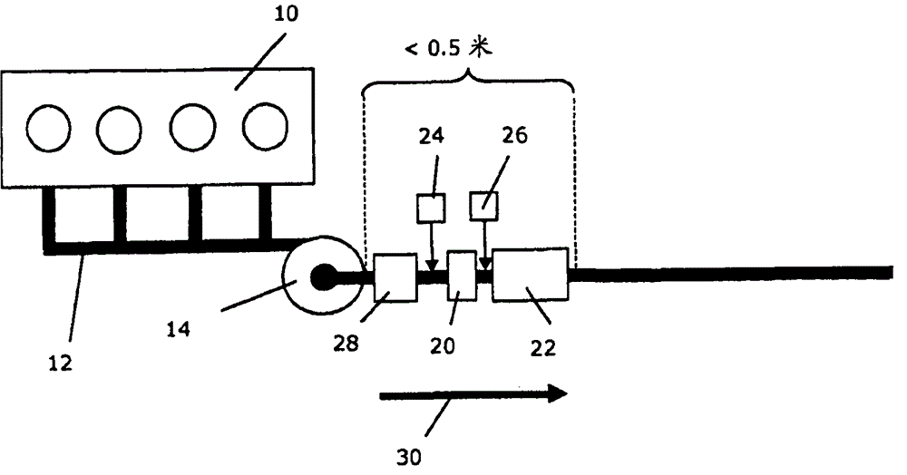
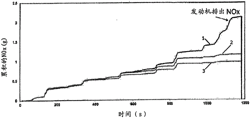
[0046] At engine start, the total NO of the system according to the invention x Conversion versus total NO for systems including only SCR wall flow filters x conversion rates for comparison. The SCR wall flow filter comprises an inert silicon carbide substrate with a porosity of 52% and an average pore size of 20 microns. The wall flow filter has a volume of 2.5L. The compact monolith has a volume of 0.625 L. The compact monolith and SCR wall flow filters were aged at 800°C for 16 hours prior to testing. Both systems were tested in the vehicle's 1.9L engine, subjected to test conditions associated with the MVEG drive cycle, with urea injected as a reducing agent at 180°C. The resulting NO of the two systems x Emissions and controls plotted against time.

[0047] NO provided by the present invention x conversion potential in figure 2 is shown in , which shows the NO x The overall output is reduced. Here, line 1 represents.


PUM

PropertyMeasurementUnit
thicknessaaaaaaaaaa
thicknessaaaaaaaaaa
sizeaaaaaaaaaa

Abstract

A system for treating exhaust gases from a combustion engine and a method for using the same results in improved NOx conversion during engine startup. The system includes a compact SCR flow-through monolith (20) installed upstream of a close- coupled SCR wall-flow filter (22), wherein the compact SCR flow-through monolith may be extruded or made of a thin-walled substrate, such that the SCR flow- through monolith has a smaller volume with lower heat capacity and higher catalyst loading relative to the SCR wall-flow filter.

Description

technical field [0001] The present invention relates to the purification of combustion engine exhaust gases. Background technique [0002] One of the trickiest components of car exhaust is NO x , which includes nitric oxide (NO), nitrogen dioxide (NO 2 ) and nitrous oxide (N 2 O). NO x The generation of is particularly problematic for lean burn engines, such as diesel engines. To mitigate NO in exhaust gas x With regard to environmental impact, it is desirable to reduce these undesirable components, preferably by methods that do not generate other harmful or toxic substances. [0003] except NO x Gas production, lean-burn combustion engines have the disadvantage of producing particulate matter or soot due to their combustion characteristics, on which various organic substances can be absorbed, including unburned hydrocarbons and sulfur species originating from the presence of fuel or lubricating oils Sulfur dioxide is oxidized to produce sulfuric acid. Diesel exhaus...

Claims


Application Information

Patent Timeline
Patent Type & Authority Applications(China)
IPC IPC(8): F01N3/022F01N3/035F01N3/20F01N13/02F01N3/28
CPCF01N3/0222F01N3/2066F01N2330/06F01N13/02F01N2330/02Y02T10/24F01N3/2825F01N2510/0682F01N3/035F01N2340/02Y02T10/12Y02A50/20B01D53/9477F01N3/022F01N3/20B01D2255/915F01N2610/02
Inventor P·R·菲利普斯J·A·怀里
Owner JOHNSON MATTHEY PLC
Why Eureka
Try Eureka