Device for manufacturing automobile aluminum alloy wheel hubs through liquid filling, local pressurizing and feeding and method thereof

A local pressurization, automobile wheel technology, applied in the direction of manufacturing tools, casting equipment, metal processing equipment, etc., can solve the problems of mechanical properties and cost constraints of wheel parts, low integration and other problems, to avoid shrinkage loose casting defects, The effect of realizing automation and eliminating shrinkage cavities

Inactive Publication Date: 2016-04-20
HARBIN INST OF TECH
View PDF18 Cites 24 Cited by
  • Summary
  • Abstract
  • Description
  • Claims
  • Application Information

AI Technical Summary

Problems solved by technology

[0005] The present invention aims to solve the problem of low integration of the existing automobile wheel hub manufacturing device and its method, and the mutual restriction between the mechanic

Method used


Image

  • Device for manufacturing automobile aluminum alloy wheel hubs through liquid filling, local pressurizing and feeding and method thereof
  • Device for manufacturing automobile aluminum alloy wheel hubs through liquid filling, local pressurizing and feeding and method thereof
  • Device for manufacturing automobile aluminum alloy wheel hubs through liquid filling, local pressurizing and feeding and method thereof

Examples


specific Embodiment approach 1

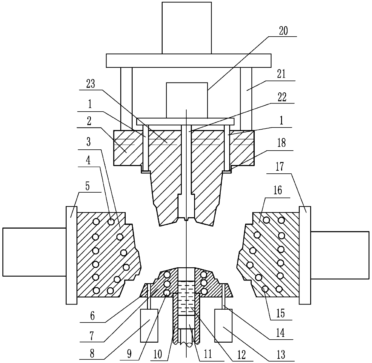
[0028] Specific implementation mode one: as Figure 1~4 As shown, the liquid filling partial pressurization and compression aluminum alloy automobile wheel manufacturing device of the present embodiment includes a local pressurization cylinder 20, an upper mold 2, an upper working cylinder 21, a first wheel rim split mold 3, and a second wheel rim split mold 16. The first heating device 4, the second heating device 9, the third heating device 15, the fourth heating device 23, the first flange split mold cylinder 5, the second flange split mold cylinder 17, the first ejector rod 6. The second ejector rod 14, the first ejector cylinder 8, the second ejector cylinder 13, the lower mold 7, the outer sleeve of the injection chamber 10, the injection piston 11, the local pressure ring 18 of the wheel rim, and the local pressure rod of the spoke 22 and a plurality of rim partial pressure rods 1;

[0029] The upper mold 2 and the lower mold 7 are aligned up and down, the first flange...

specific Embodiment approach 2

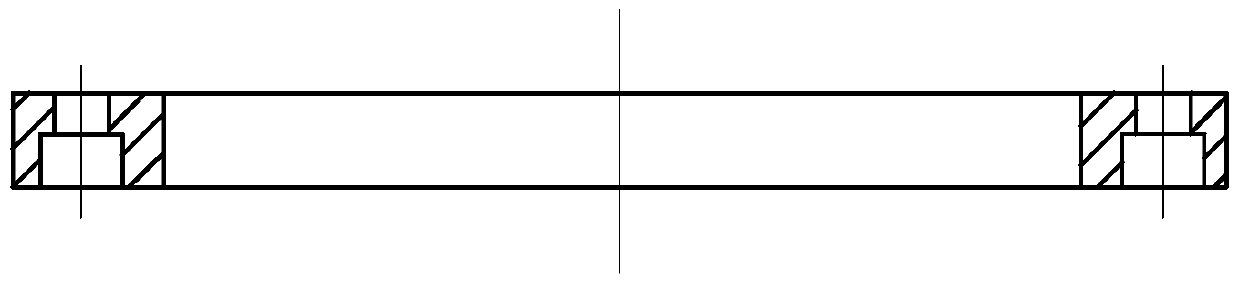
[0031] Specific implementation mode two: as figure 1 and Figure 4 As shown, the number of rim local pressure rods 1 in this embodiment is eight. Such a design can ensure that the load applied during partial pressurization acts on the liquid-solid slurry evenly. Other components and connections are the same as those in the first embodiment.

specific Embodiment approach 3

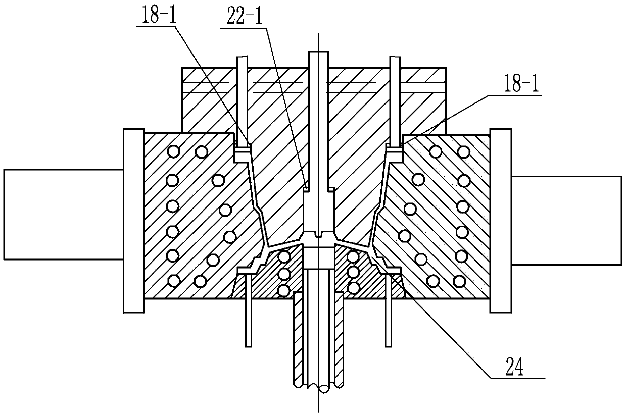
[0032] Specific implementation mode three: as image 3 and Figure 4 As shown, in this embodiment, the lower end of the rim local pressure rod 1 and the rim local pressure ring 18 are fixedly connected by lag bolts. Such a design can prevent the bolts from rotating when the partial pressure ring of the wheel rim is installed.

[0033] Other compositions and connections are the same as those in Embodiment 1 or 2.


PUM

PropertyMeasurementUnit
Thicknessaaaaaaaaaa
Rockwell hardnessaaaaaaaaaa

Abstract

The invention relates to a manufacturing device for automobile wheel hubs and a method thereof, in particular to a device for manufacturing automobile aluminum alloy wheel hubs through liquid filling, local pressurizing and feeding and a method thereof. The device and the method thereof solve the problems that existing automobile wheel hub manufacturing devices and the method thereof are low in integration level and the mechanical property of wheel hub parts and the cost are mutually restricted. The upper end of a local spoke pressurizing rod and a plurality of local rim pressurizing rods are connected to a local pressurizing cylinder, the local spoke pressurizing rod is located in a center hole of an upper die, the local rim pressurizing rods are uniformly arranged in the upper die in the circumferential direction, the lower ends of the local rim pressurizing rods are fixedly connected to local rim pressurizing rings, and an injection chamber sleeve is coaxially communicated with the lower end of a central through hole of a lower die. The method comprises the steps of carrying out fusion and heat preservation; spraying release agents on the surface of a first rim splitting die, the surface of a second rim splitting die, the surface of the upper die and the surface of the lower die, closing and heating the dies and carrying out heat preservation; opening the dies and pouring molten aluminum; injecting the molten aluminum into cavities of the wheel hubs after the dies are closed; carrying out local pressurizing and retreating the dies; ejecting and forming the wheel hubs. The device and the method are used for manufacturing the automobile aluminum alloy wheel hubs.

Description

technical field [0001] The invention relates to a manufacturing device and method for an aluminum alloy automobile wheel hub, in particular to a manufacturing device and a method for liquid filling and partially pressurizing an aluminum alloy automobile hub. Background technique [0002] With the shortage of energy and the increasingly serious problem of environmental pollution, energy saving, emission reduction and consumption reduction are the eternal themes in the development of manufacturing industry. The manufacture of equipment pays more and more attention to lightweight. This includes lightweight design and material selection of structural parts. The lightweight selection of materials mainly refers to the use of lighter metal structural materials to replace existing structural materials. Metal structural materials occupy an important position in the equipment manufacturing industry. At present, the main lightweight task is to replace as many existing steel structur...

Claims


Application Information

Patent Timeline
IPC IPC(8): B22C9/28B22D27/11
CPCB22C9/28B22D27/11
Inventor 姜巨福王迎
Owner HARBIN INST OF TECH
Why Eureka
Try Eureka