
Microwave oven adopting cylindrical oven chamber and taking helical antenna as radiator

A helical antenna and cylindrical technology, which is applied in the field of microwave ovens using a cylindrical furnace cavity and a helical antenna as a radiator, can solve the problems of microwave radiation, uneven heating of heated objects, furnace weight, and complex structure. Achieve the effects of improving the uniformity of heating and energy utilization, uniform heating, and light weight of the furnace body

Inactive Publication Date: 2016-04-20
UNIV OF ELECTRONICS SCI & TECH OF CHINA
View PDF11 Cites 9 Cited by
  • Summary
  • Abstract
  • Description
  • Claims
  • Application Information

AI Technical Summary

Problems solved by technology

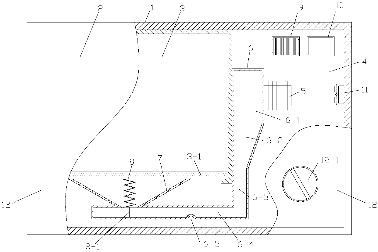
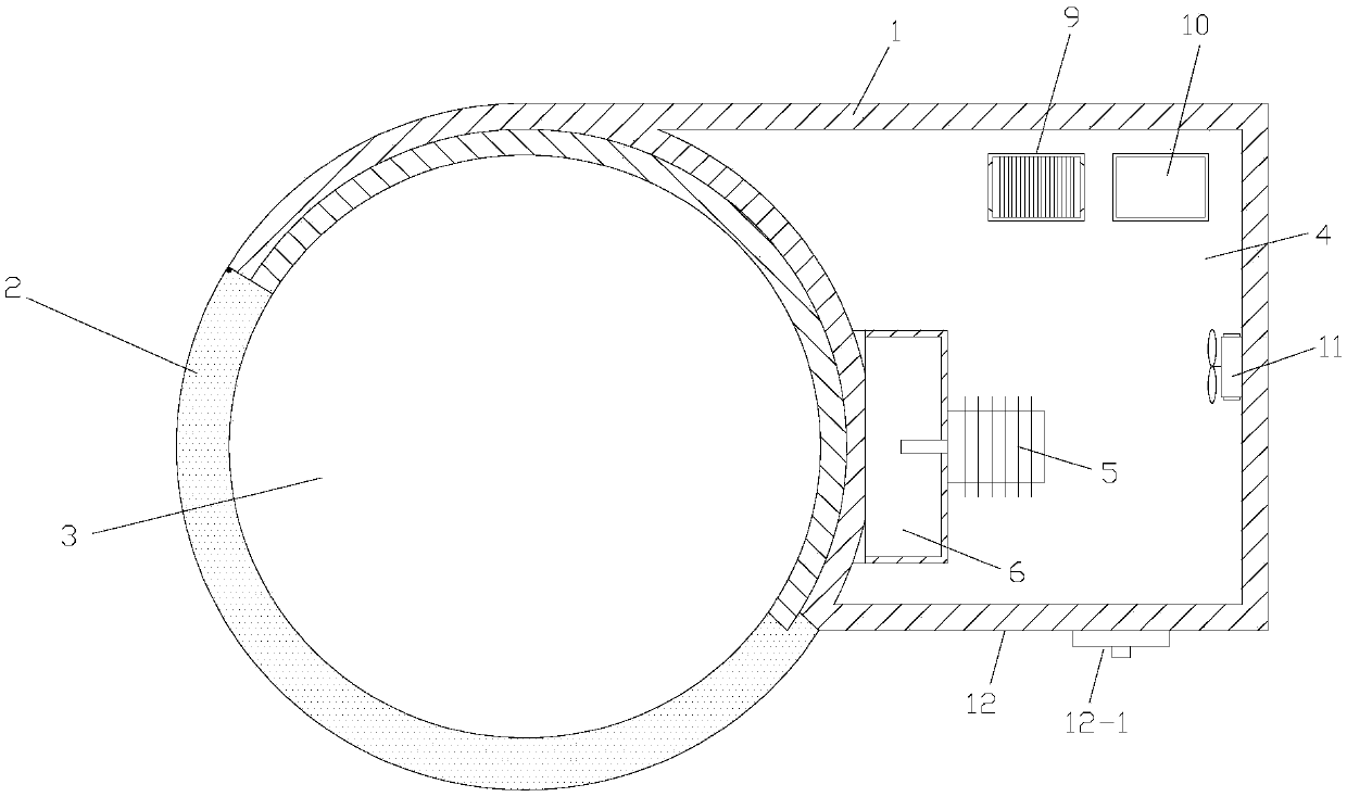
[0005] The solution of the microwave oven of the present invention is to improve the cubic furnace (heating) cavity of the traditional microwave oven into a cylindrical furnace (heating) cavity, and simultaneously adopt the helical antenna with circular polarization characteristics as the microwave radiator, and install it in the furnace cavity It cooperates with the magnetron and the "L" shaped waveguide composed of a vertical waveguide and a horizontal waveguide with a waveguide exit, and a microwave reflector. The cavity directly radiates high-speed rotating electromagnetic waves (microwaves), to replace traditional flat-panel microwave ovens that need to be equipped with stirring mechanisms such as motors and blades that stir the microwaves generated (emitted) by the magnetron, and turntable microwave ovens with waveguide nozzles on the side. The necessary loading turntable and its transmission system can overcome the problems of traditional turntable and flat-plate microwave ovens, such as complex structure, furnace weight, microwave radiation, and uneven heating of heated objects.

Method used


Image

  • Microwave oven adopting cylindrical oven chamber and taking helical antenna as radiator
  • Microwave oven adopting cylindrical oven chamber and taking helical antenna as radiator

Examples


Embodiment 1

[0011] Embodiment 1: This embodiment takes a household microwave oven with a rated input power of 1200W (output power of 750W) and a microwave operating frequency of 2450MHz as an example: shell 1. (height×width) 330×500mm, the shell diameter of the furnace cavity is φ350mm, the electrical box The top of the position is 260mm deep; the furnace door 2 is a semi-cylindrical shell-shaped furnace door with an outer diameter of φ350mm and a height of 285mm; the furnace cavity 3 has an internal diameter of φ300mm and a height of 220mm. (diameter * thickness) glass-ceramic plate of φ300 * 5mm; Magnetron 5. Model 2M219, operating frequency F=2450MHz; The vertical waveguide total height in " L " shape waveguide 6 is 187mm, wherein: (microwave) The excitation section 6-1 is a rectangular waveguide with a cavity height of 70mm up and down, a lateral width of 40mm, and a depth of 80mm. (Vertical waveguide) An inverted trapezoidal transitional waveguide section with the same cross-section ...

Embodiment 2

[0012] Embodiment two: present embodiment furnace chamber 3 inner diameters, high 220mm, (furnace chamber) bottom plate 3-1 is all identical with embodiment one, and the present embodiment of furnace chamber top board adopts the parabolic top board that protrudes upwards, and the parabolic surface top board of this top board The microwave energy reflected from the upper surface has the function of radial convergence, which can further improve the heating efficiency; other parts are also the same as the first embodiment.


PUM


Abstract

The invention belongs to a microwave oven for food cooking. The microwave oven comprises a microwave oven casing, a cylindrical oven chamber arranged in the casing, an electric appliance box, a microwave magnetron, an L-shaped waveguide tube comprising a vertical waveguide tube and a horizontal rectangular waveguide tube provided with a waveguide outlet, a helical antenna, a microwave reflector, a power supply, a fan, a circuit board, an oven door and a panel provided with a circuit control key or knob, wherein the microwave magnetron and the L-shaped waveguide tube are arranged in the electric appliance box. The microwave oven adopts the cylindrical oven chamber, so that eight useless energy storage dead angles of the traditional oven chamber are eliminated; the circularly polarized helical antenna is taken as a microwave radiator, the rotation speed of the helical antenna is working frequency of a microwave source, uniformity of microwave radiation and heating of heated objects are effectively improved, the utilization rate of energy is effectively increased, and heating time is shortened. Thus, the microwave oven has the characteristics that the structure is simple, an oven body is light, microwave radiation and heating of the heated objects are uniform, the utilization rate of the energy and the energy efficiency are high, the heating time is short, the service life is long, the production cost is low and the like.

Description

technical field [0001] The invention belongs to a microwave oven for food cooking, in particular to a cylindrical furnace cavity and a circularly polarized helical antenna as a radiator to radiate ultra-high-speed rotating electromagnetic waves (the rotation rate is the same as the operating frequency of the microwave source), so that A microwave oven in which the microwave radiation in the heating (resonance) cavity and the object to be heated are heated evenly. When the microwave operating frequency is 2450MHz, the microwave rotation rate is 2.45×10 9 r / sec (2.45 billion times / second) (that is, the speed is 1470×10 8 rpm's super high-speed rotation). Background technique [0002] It has been nearly 70 years since the microwave oven was invented. Traditional microwave ovens include a shell, a cubic microwave heating (furnace) cavity inside the shell, and a microwave-containing magnetron (microwave generator) and its feeder that are isolated from the microwave heating cavit...

Claims


Application Information

Patent Timeline
Patent Type & Authority Applications(China)
IPC IPC(8): F24C7/02F24C7/08
CPCH05B6/72H05B6/6402
Inventor 张兆镗
Owner UNIV OF ELECTRONICS SCI & TECH OF CHINA
Learn More