Eureka AIR delivers breakthrough ideas for toughest innovation challenges, trusted by R&D personnel around the world.

High-isolation microwave test fixture for ultrahigh-power GaN microwave devices

A microwave device, high isolation technology, applied in the direction of single semiconductor device testing, electrical measuring instrument components, instruments, etc., can solve the problem of insufficient isolation of radio frequency signals, and achieve the effects of avoiding burning, low cost and easy implementation

Active Publication Date: 2016-04-20
THE 13TH RES INST OF CHINA ELECTRONICS TECH GRP CORP
View PDF7 Cites 7 Cited by
  • Summary
  • Abstract
  • Description
  • Claims
  • Application Information

AI Technical Summary

Problems solved by technology

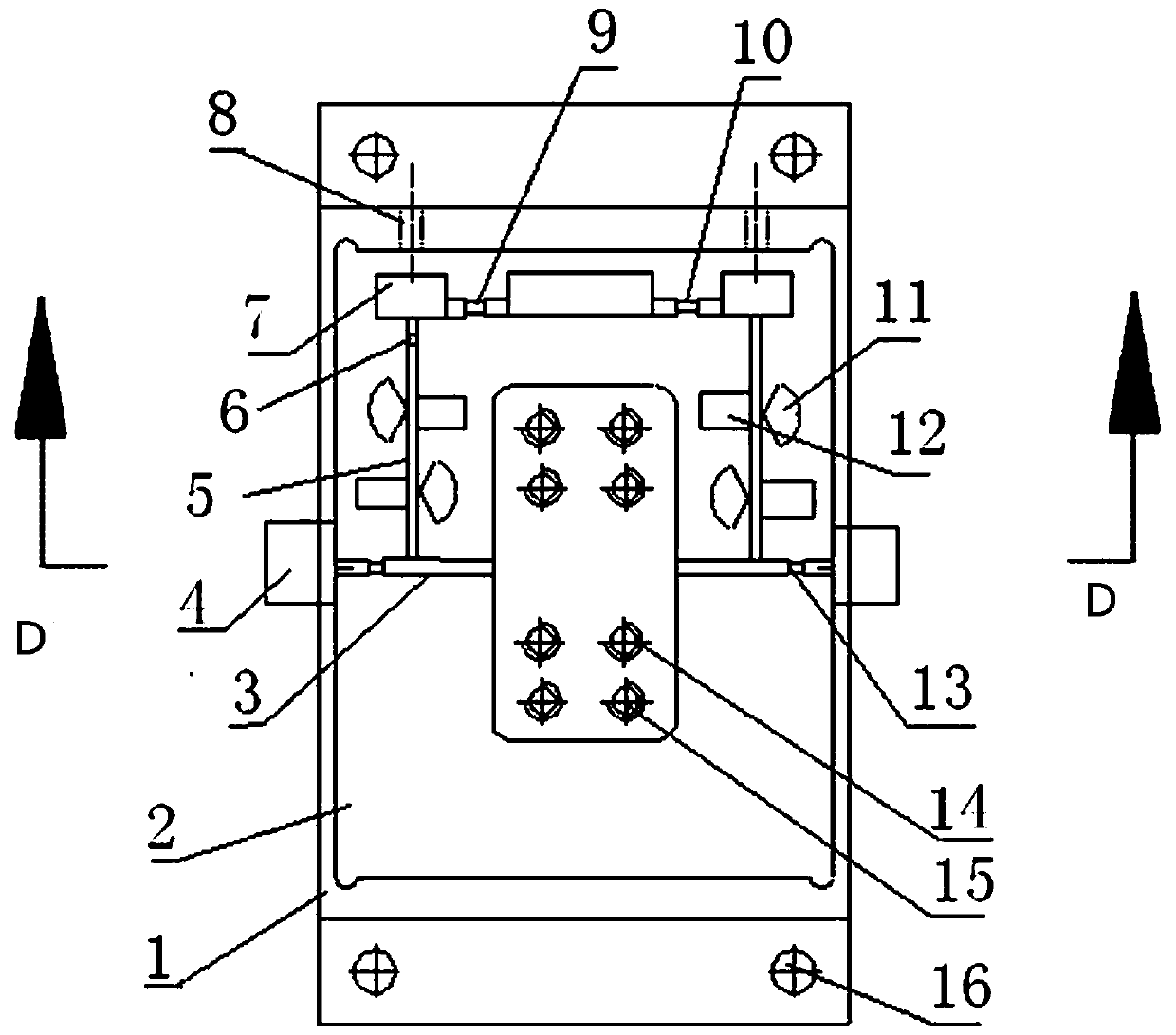
[0006] The technical problem to be solved by the present invention is to provide a high-isolation microwave test fixture for ultra-high-power GaN microwave devices, which is used for microwave testing of high-voltage and ultra-high-power microwave devices, and solves the isolation of drain leakage radio frequency signals in the ultra-high-power testing process of microwave devices Insufficient temperature can avoid the burning of the DC bias module and ensure that the test results are true and effective. It is also suitable for microwave testing of similar devices.

Method used


Image

  • High-isolation microwave test fixture for ultrahigh-power GaN microwave devices
  • High-isolation microwave test fixture for ultrahigh-power GaN microwave devices
  • High-isolation microwave test fixture for ultrahigh-power GaN microwave devices

Examples


Embodiment Construction

[0024] The present invention will be further described in detail below in conjunction with the accompanying drawings and specific embodiments.

[0025] The feeding matching circuit of the microwave test fixture usually adopts a single sector structure, and there is a problem of insufficient isolation of the drain leakage radio frequency signal during the testing process of high-voltage ultra-high-power microwave devices. The invention provides a high-isolation test for high-voltage ultra-high-power microwave devices. The fixture successfully solves the problem of ultra-high power testing of microwave devices.

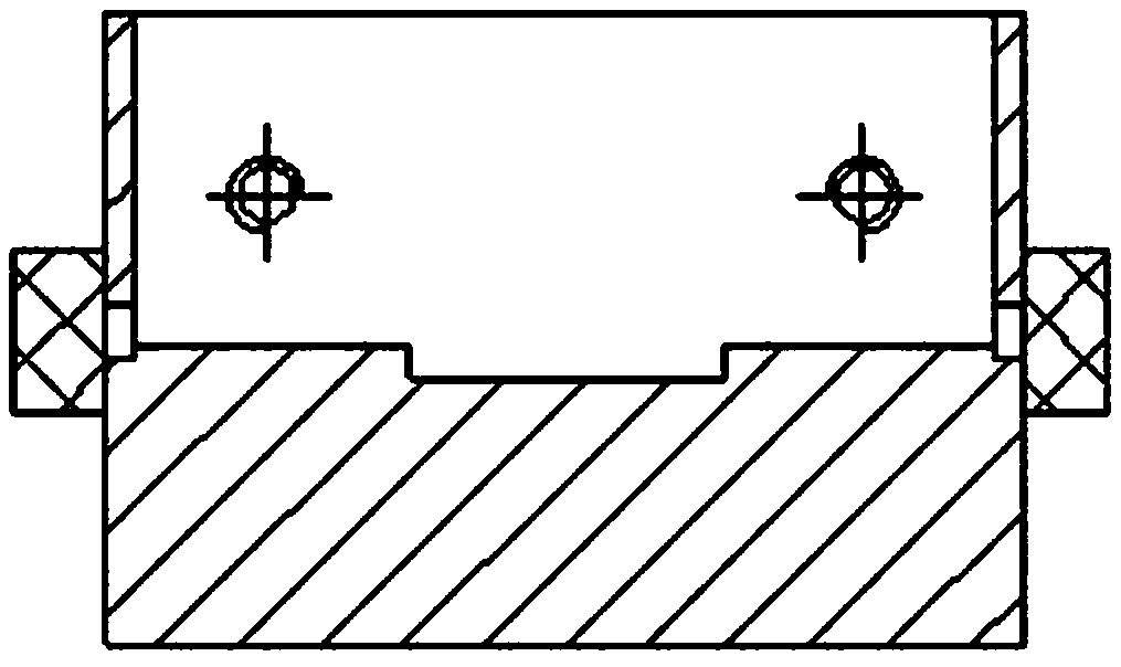
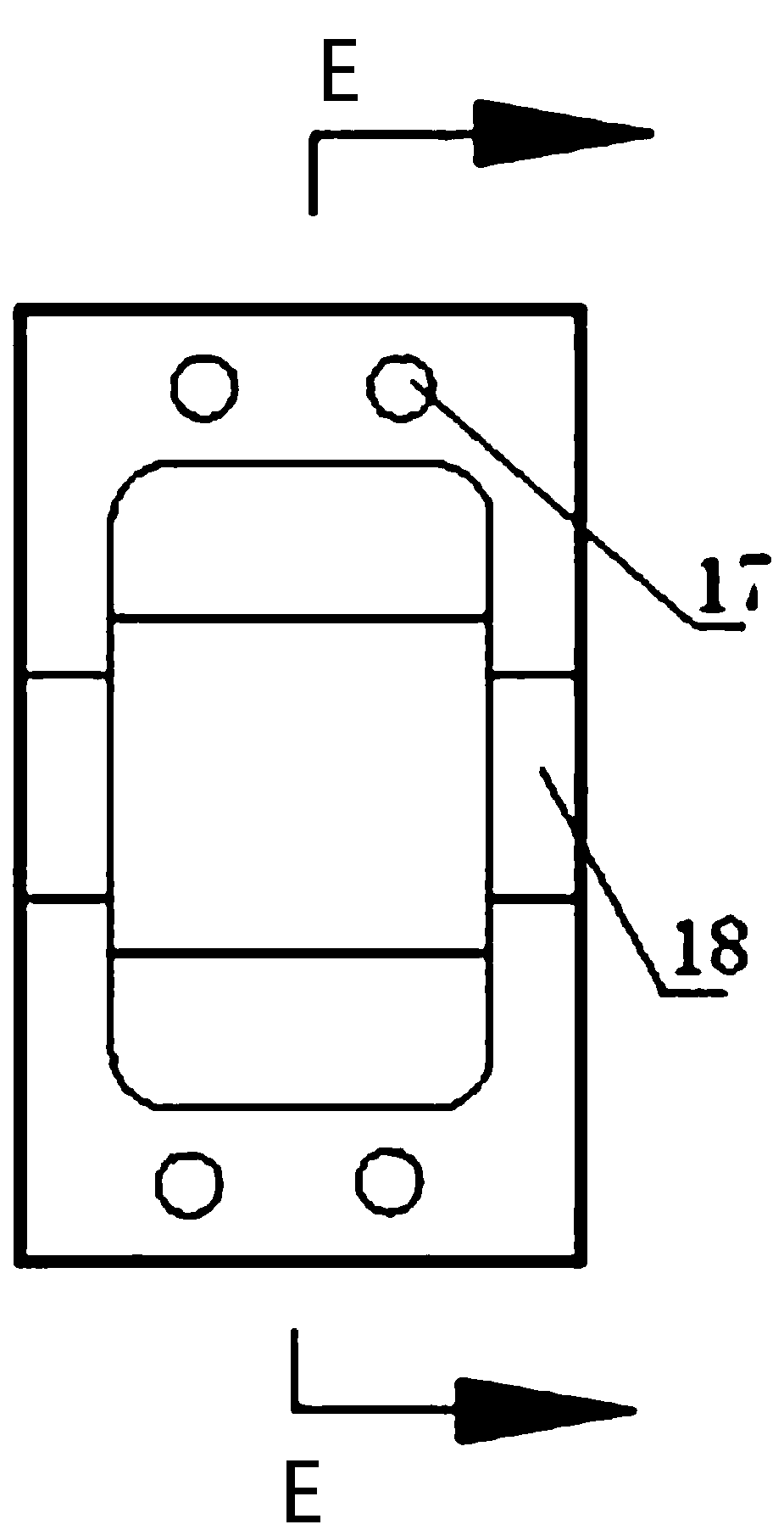
[0026] see Figure 1-Figure 4 As shown, the present invention includes a test box body 1, a PCB board 2, a pressing block, a DC bias terminal, and a radio frequency input and output terminal. The PCB board 2 is placed in the test box body, and the PCB board 2 includes a feeding matching circuit and a radio frequency input The output microstrip 3; the feeding matching c...


PUM


Abstract

The invention discloses a high-isolation microwave test fixture for ultrahigh-power GaN microwave devices, which belongs to the technical field of testing of semiconductor devices. The high-isolation microwave test fixture comprises a test box body, a PCB (printed circuit board), a holddown, a direct-current bias leading-out terminal and a radio frequency input / output leading-out terminal, wherein the PCB is arranged in the text box body, and the PCB comprises a feed matching circuit and a radio frequency input / output microstrip; the feed matching circuit is divided into two parts, i.e. a grid feed matching circuit and a drain feed matching circuit, the grid feed matching circuit comprises double sector-shaped wires, two RC (Resistor-Capacitor) filter networks, a grid bias resistor and a grid filter capacitor, and the drain feed matching circuit comprises double sector-shaped wires, two RC filter networks and a drain filter capacitor; the direct-current bias leading-out terminal is led out of the feed matching circuit from two feedthru capacitors; the radio frequency input / output leading-out terminal is a coaxial transmission-to-microstrip transmission connector. The invention solves the problem of insufficient isolation of leaked radio frequency signals of a drain electrode existing in the process of ultrahigh-power testing of microwave devices, can prevent a direct-current bias module from being burnt, and ensures the authenticity and effectiveness of test results.

Description

technical field [0001] The invention belongs to the technical field of semiconductor device testing, in particular to a high-isolation microwave test fixture for ultra-high-power GaN microwave devices. Background technique [0002] GaN semiconductor technology has become an inevitable development trend of high-power technology. Compared with the second-generation semiconductor GaAs, GaN (gallium nitride) devices have higher breakdown voltage, higher electron saturation velocity and higher output power, and its power density is 10 times that of GaAs (gallium arsenide) above, and the high working voltage can effectively improve the efficiency of the whole system. [0003] The high-power GaN microwave device is a voltage control device, packaged in the form of a cermet shell, and its internal structure includes a gate matching circuit, a drain matching circuit, a matching capacitor, an active chip, and a bonding gold wire. The base of the tube shell is the source, and the two...

Claims


Application Information

Patent Timeline
Patent Type & Authority Applications(China)
IPC IPC(8): G01R1/04G01R31/26
CPCG01R1/0425G01R31/26
Inventor 林丽艳李剑锋吴阿慧顾占彪
Owner THE 13TH RES INST OF CHINA ELECTRONICS TECH GRP CORP
Why Eureka
Eureka Blog
Learn More