Method for establishing comprehensive pipe rack information database

A technology of integrated pipe gallery and database, applied in the field of establishing comprehensive pipe gallery information database, can solve the problems of high field work intensity, high operator requirements, and intrusion into the interior of the pipeline, so as to reduce the operating burden, improve the recognizability, The effect of improving work efficiency

Active Publication Date: 2016-04-20
SHANDONG ZHENGYUAN GEOPHYSICAL INFORMATION TECH CO LTD
View PDF6 Cites 16 Cited by
  • Summary
  • Abstract
  • Description
  • Claims
  • Application Information

AI Technical Summary

Problems solved by technology

At present, the degree of automation or semi-automation of underground pipeline detection is low. The detection pipeline mainly uses electromagnetic pipeline detectors. According to the detection principle, it is mainly divided into two categories: (1) The electromagnetic induction principle detects metal pipelines, electricity, optical cables and some metal marking lines. For metal pipelines, non-metallic probes must be used to detect non-metallic trunk lines. This method is more laborious to use and needs to invade the interior of the pipeline; (2) Electromagnetic waves detect underground pipelines of all materials, commonly known as pipeline radar. This method has higher environmental requirements. High, poor depth-sounding capability, high requirements for operators
The coordinate data of the pipeline is measured by GPS, total station and other surveying and mapping instruments. The coordinate data of the pipeline and the characteristic elements of the pipeline need to be obtained separately. The field detection work requires a lot of human and financial resources. The field work is intensive and the work efficiency is relatively low.

Method used


Image

  • Method for establishing comprehensive pipe rack information database
  • Method for establishing comprehensive pipe rack information database
  • Method for establishing comprehensive pipe rack information database

Examples


Embodiment Construction

[0043] In order to better understand the technical solution of the present invention, the present invention will be further described below in conjunction with the accompanying drawings.

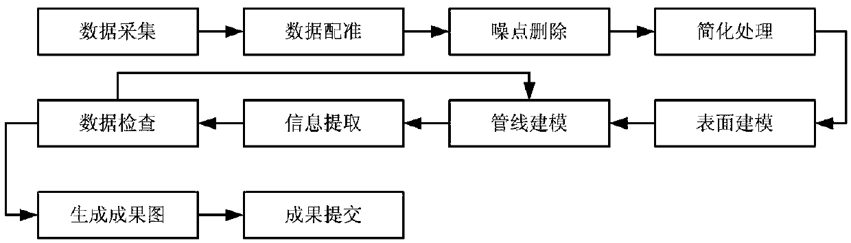
[0044] A method for establishing an information database of an integrated pipe gallery, the steps of which are as follows figure 1 shown.

[0045] Step 1. Data collection: survey the survey area to understand the situation of the survey area (with measurement range), and collect data.

[0046] Obtain high-precision point cloud data with image realism through the airborne laser scanner or ground laser scanner. The point cloud data is the restoration of the real size of the actual object, and it is the most complete, precise and fast archive of the current status of the object. means of preservation. The data of each scanning site is placed in an independent coordinate system centered on the instrument (with the instrument as the origin, the X-axis is in the horizontal scanning plane, the Y-...


PUM


Abstract

A method for establishing a comprehensive pipe rack information database comprises steps as follows: S1, point cloud data of an underground pipeline network are acquired through a laser scanning instrument; S2, data registration and transferring are performed; S3, noise data are rejected; S4, the point cloud data without the noise data are subjected to data thinning processing; S5, a pipeline surface model is established; S6, a pipeline model is drawn; S7, pipeline information is extracted; S8, system configuration parameters are read, extracted pipe point and pipeline data are checked, and checked results are listed on a table according to the mistake type; S9, a two-dimensional planar graph of a pipeline is drawn, the type and the material of the pipeline and the pipe diameter information are marked, and finally, a pipeline result map is obtained; S10, the pipeline result map, a three-dimensional diagram of the pipeline model and the two-dimensional planar graph of the pipeline are stored in the database. According to the method, base establishing for underground pipelines can be rapidly completed, and the pipe rack data are vectorized.

Description

technical field [0001] The invention relates to the field of pipeline network data database construction, in particular to a method for establishing a comprehensive pipeline gallery information database. Background technique [0002] Underground pipelines are regarded as the lifeline of cities, and with the continuous development of cities, the number of pipelines increases rapidly. At present, the distribution of underground pipe networks in many cities and enterprises is unclear, and the management of archives is not standardized enough. There are more and more types of underground pipelines in cities, and the materials are more and more abundant, which brings many difficulties to the detection of underground pipelines. This objectively also requires the detection equipment to adopt new technologies to achieve fast, accurate and convenient detection. At present, the degree of automation or semi-automation of underground pipeline detection is low. The detection pipeline ma...

Claims


Application Information

Patent Timeline
Patent Type & Authority Applications(China)
IPC IPC(8): G06F17/30
CPCG06F16/212
Inventor 张善法王子启迟炳章刘甲军李才明马骏孟慧叶延磊邵先奎于志刚
Owner SHANDONG ZHENGYUAN GEOPHYSICAL INFORMATION TECH CO LTD
Why Eureka
Try Eureka