High-gain microstrip array antenna

A microstrip array, high-gain technology, applied in the field of antennas, can solve the problems of large installation space, high cost, heavy weight of parabolic antennas, etc., and achieve the effect of simple and mature technology, simple structure and small thickness

Inactive Publication Date: 2016-04-20
CHENGDU UNIV OF INFORMATION TECH
View PDF5 Cites 3 Cited by
  • Summary
  • Abstract
  • Description
  • Claims
  • Application Information

AI Technical Summary

Problems solved by technology

The section size of the parabolic antenna is very large and requires a large installation space, which is not practical for some special purposes
In addition, the weight of the parabolic antenna is relatively heavy, an

Method used


Image

  • High-gain microstrip array antenna
  • High-gain microstrip array antenna

Examples


Embodiment Construction

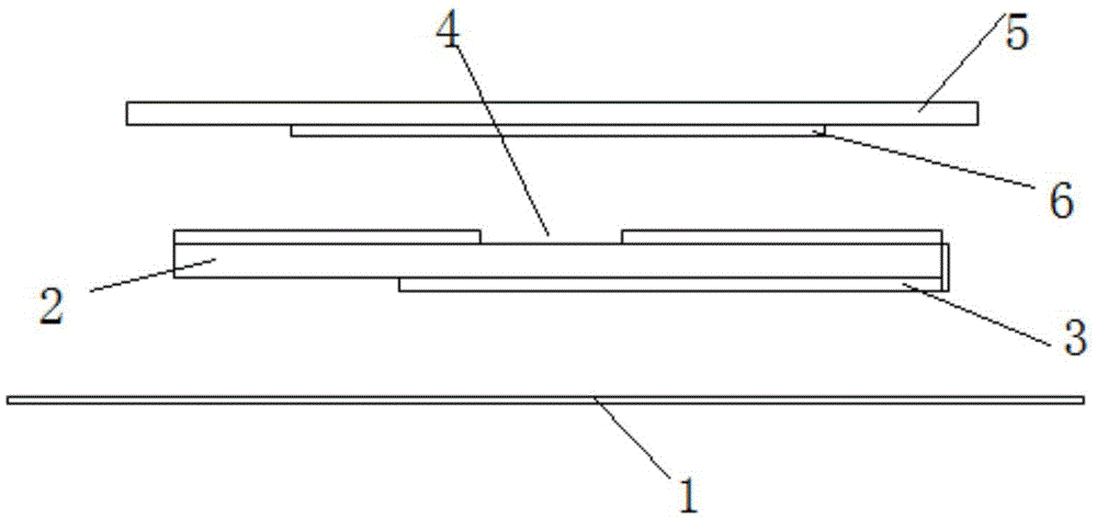
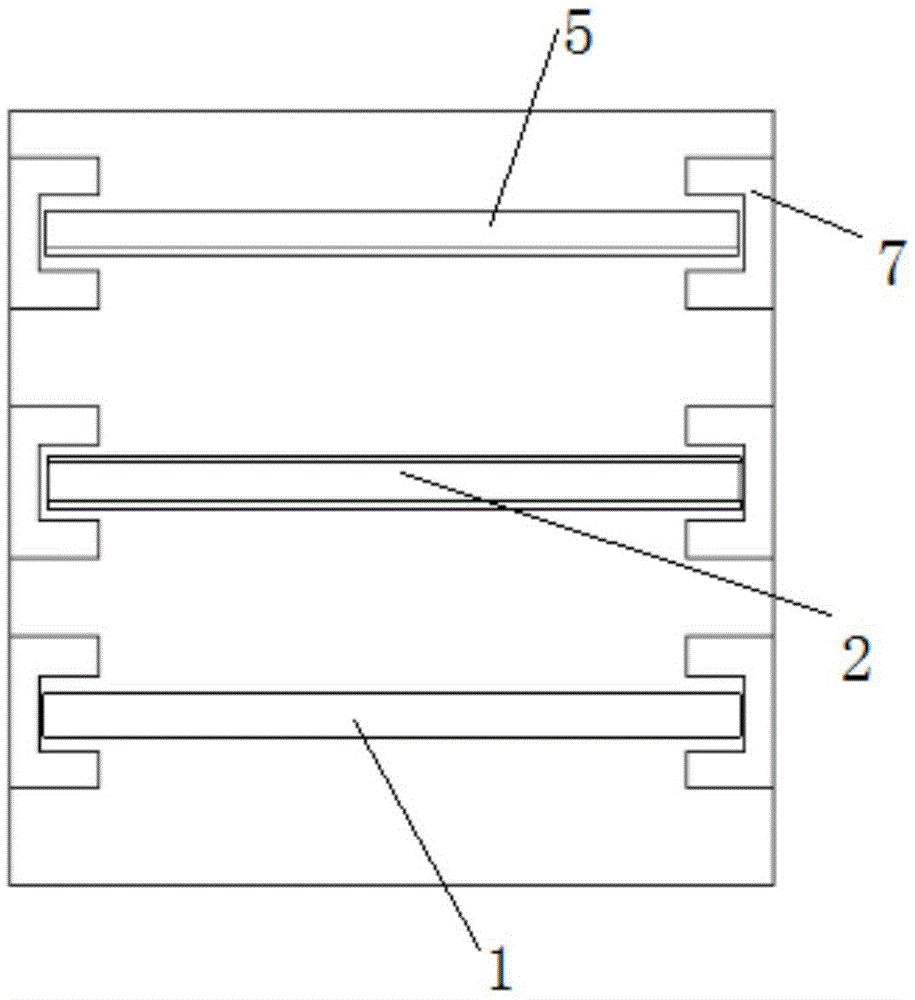
[0013] The specific embodiment of the present invention will be described with reference to the accompanying drawings. Such as figure 1 As shown, the high-gain microstrip array antenna includes a metal reflector 1, and above the metal reflector 1 is a feed network 3, and the feed network 3 is installed on the lower surface of the first dielectric plate 2, and the first There is a slit 4 on the upper surface of the dielectric plate 2, and a metal patch 6 is arranged above the slit 4, and the metal patch 6 is installed on the lower surface of the second dielectric plate 5; There is an air layer between them, and there is also an air layer between the first dielectric board 2 and the second dielectric board 5 .

[0014] The relative permittivity of air is 1, and other media are greater than 1. Therefore, the air layer is regarded as the air dielectric layer. The introduction of the air dielectric layer will reduce the equivalent dielectric constant of the entire antenna, and the...


PUM


Abstract

The invention relates to an antenna, and specifically relates to a high-gain microstrip array antenna. The high-gain microstrip array antenna comprises a metal reflection plate, a feed network is arranged above the metal reflection plate, the feed network is installed at the lower surface of a first medium plate, a slit is arranged at the upper surface of the first medium plate, a metal patch is arranged above the slit, and the metal patch is installed at the lower surface of a second medium plate; and an air layer is arranged between the metal reflection plate and the first medium plate, and an air layer is also arranged between the first medium plate and the second medium plate. The high-gain microstrip array antenna provided by the invention employs a microstrip array form, is easy to process, low in cost and simple in structure; and the product has the feature of a low profile, the distance of the reflection plate is generally one quarter of an operating wavelength, the overall thickness of the antenna is not large, and the weight is light.

Description

technical field [0001] The invention relates to an antenna, in particular to a high-gain microstrip array antenna. Background technique [0002] At present, high-gain antennas used for communication, that is, the gain is generally greater than 30dB, are realized by adopting the structural form of a parabolic antenna. [0003] The structure of the parabolic antenna is complex, and the feed horn antenna needs to be installed on the focal point of the parabolic reflector through a bracket, including the parabolic reflector. The section size of the parabolic antenna is very large and requires a large installation space, which is not practical for some special purposes. In addition, the weight of the parabolic antenna is relatively heavy, and the parabolic reflector is a whole piece of shaped metal. The processing of the parabolic antenna is complicated, and the parabolic reflector needs to be specially molded according to the size, so the cost is also high. Contents of the i...

Claims


Application Information

Patent Timeline
IPC IPC(8): H01Q1/38H01Q19/10H01Q1/50H01Q5/378H01Q21/00
CPCH01Q1/38H01Q1/50H01Q19/104H01Q19/106H01Q21/00
Inventor 唐涛汪江宇唐军
Owner CHENGDU UNIV OF INFORMATION TECH
Why Eureka
Try Eureka