Electric vehicle group charging microgrid control method supporting secure dynamic capacity-increase

An electric vehicle and dynamic capacity-increasing technology, applied in electric vehicles, battery circuit devices, current collectors, etc., can solve problems such as high charging power, immature renewable energy power generation technology, and easy damage to key electrical equipment

Inactive Publication Date: 2016-04-20
樊朝晖 +3
View PDF11 Cites 38 Cited by
  • Summary
  • Abstract
  • Description
  • Claims
  • Application Information

AI Technical Summary

Problems solved by technology

The technology for connecting a high proportion of renewable energy to power generation in large-scale transmission grids is still immature and difficult to achieve in the short term, which is not conducive to the early realization of national energy conservation and emission reduction goals
[0004] Due to sudden failure of generators, intermittent wind power and photovoltaic power generation, etc., the power balance of grid power supply is easily damaged, and traditional power loads cannot respond to such power adjustment needs in a timely manner and adjust power consumption plans; when the problem is serious to a certain extent, The load power supply can only be interrupted by means of switching off and limiting power, which will bring production losses and inconvenience to power users
[0005] Because the charging power of electric vehicles is larger than that of traditional loads, it is difficult for existing power facilities to support many electric vehicles to charge slowly at the same time, and the large inrush current generated by the disorderly connection of high-power charging is also likely to damage key electrical equipment or cause damage to protective equipment. Misoperation, causing unnecessary power outages
When new large-scale commercial centers, enterprises, institutions or residential areas need to consider disorderly electric vehicle charging behavior, in order to ensure the safety of power distribution facilities, only key equipment such as transformers with large capacity can be configured, which greatly increases the investment cost

Method used


Image

  • Electric vehicle group charging microgrid control method supporting secure dynamic capacity-increase
  • Electric vehicle group charging microgrid control method supporting secure dynamic capacity-increase
  • Electric vehicle group charging microgrid control method supporting secure dynamic capacity-increase

Examples


Embodiment Construction

[0162] The present invention will be described in further detail below with reference to the accompanying drawings and examples.

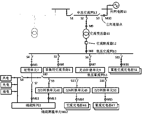
[0163] figure 1 Design the grid-connected structure and energy flow diagram of the microgrid for the typical integration of storage and distribution. by closing figure 1 When the circuit switch (S2) is turned off, the microgrid enters the network operation; otherwise, the microgrid enters the isolated network operation. When in the network operation state, if the circuit breaker (S3) at the common connection point is closed, the microgrid in network operation is then connected to the external network power supply (13) through the medium voltage AC network (12) , the microgrid enters the grid-connected operation state. Such as figure 1 As shown by the middle dotted line, multiple microgrids in the networked or grid-connected operating state can be connected end-to-end through the medium-voltage AC network (12) to form the connected microgrid gro...


PUM


Abstract

The invention discloses an electric vehicle group charging microgrid control method supporting a secure dynamic capacity-increase. The electric vehicle group charging microgrid control method takes a large capacity energy storage array in an Ethernet as a core control object to construct an electric vehicle group charging system, and the specific process is that after a manager submits a charging request, an electric vehicle group charging management module queries the remaining capacity of a network accessed transformer, if the remaining capacity is insufficient, the discharge power of the energy storage array is increased and charging power is reserved for a charging pile to be started; a charging loop is connected or opened after the reservation, the charging is started, and the impacts of quick charging and simultaneous slow charging for a number of vehicles or risks of continuously exceeding the capacity of the transformer are voided; and the charging is stopped when the power of the energy storage array is insufficient. The invention achieves a dynamic capacity-increase by means of the energy storage array, allows the actual charging load to be greater than the capacity of the transformer, delays the capacity-increase reformation of a distribution network in existing places, saves investment in the distribution network in new places, supports safe conventional power utilization and charging requirements, and takes participation in the power grid active adjustment services.

Description

technical field [0001] The invention belongs to the technical field of micro-distribution networks, and in particular relates to a control method for charging micro-networks of electric vehicle groups supporting safe dynamic capacity increase. Background technique [0002] Connecting distributed wind power and photovoltaic power generation units to the isolated micro-distribution network can improve the environmental protection of energy use and solve the problems of pollution and high cost caused by excessive reliance on diesel power generation. But at the same time, users are faced with the problems of intermittent power generation output and poor power quality. The above problems can be alleviated by adding an energy storage unit, but it is easy to fail to provide reliable power to users due to insufficient wind power, solar power generation or energy storage capacity, or failure of the energy storage unit. At the same time, the problem of environmental pollution cannot ...

Claims


Application Information

Patent Timeline
Patent Type & Authority Applications(China)
IPC IPC(8): H02J7/00H02J3/28H02J3/42H02J3/46
Inventor 樊朝晖李庄彭旭华张婧
Owner 樊朝晖
Why Eureka
Try Eureka