Tubular oil-water cyclone separation equipment

A technology of cyclone separation and oil-water separation, which is applied in the oil-water separation process and the field of tubular oil-water cyclone separation equipment, which can solve the problems of increasing monomer processing capacity and achieve the effects of reducing investment and operating costs, high performance and compact equipment

Active Publication Date: 2016-05-04
BEIJING INSTITUTE OF PETROCHEMICAL TECHNOLOGY
View PDF9 Cites 11 Cited by
  • Summary
  • Abstract
  • Description
  • Claims
  • Application Information

AI Technical Summary

Problems solved by technology

However, the above patents are all based on the conventional tangential inlet static hydrocyclone, and the single treatment capacity needs to be further improved.

Method used


Image

  • Tubular oil-water cyclone separation equipment
  • Tubular oil-water cyclone separation equipment
  • Tubular oil-water cyclone separation equipment

Examples


specific Embodiment approach

[0014] The preferred embodiment of the tubular oil-water cyclone separation device of the present invention is:

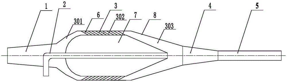
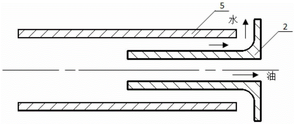
[0015] It includes a liquid inlet pipe, a spinner, a separation chamber and a liquid discharge pipe. The liquid discharge pipe includes an oil discharge pipe and a drain pipe. The liquid inlet pipe, the spinner, a separation chamber and a drain pipe are sequentially connected by flanges or welding .

[0016] The liquid inlet pipe, the spinner, the separation chamber and the drain pipe are sequentially connected to form a tubular structure as a whole, the liquid inlet pipe is connected to the liquid incoming pipe through a flange, and the drain pipe is connected to a downstream pipeline through a flange.

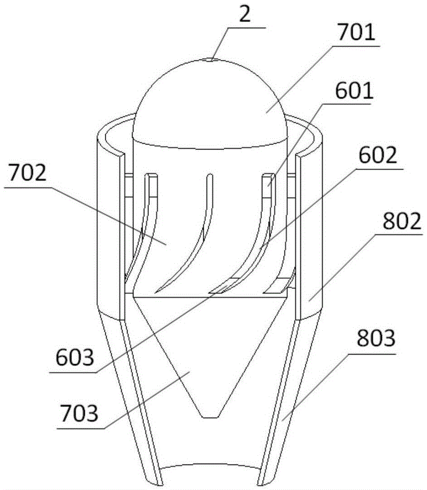
[0017] The spinner includes a blade carrier, a guide vane and an outer tube, and the guide vane is closely matched with the blade carrier and the outer tube in the radial direction.

[0018] The guide vane includes a drainage section, a swirling section and a flo...

specific Embodiment

[0026] Such as figure 1 As shown, the embodiment of the present invention provides a pipe-type pipe-type oil-water cyclone separation device, which is composed of a liquid inlet pipe 1 , a spinner 3 , a separation chamber 4 , a drain pipe 5 and an oil discharge pipe 2 .

[0027] Wherein, the liquid inlet pipe 1, the spinner 3, the separation chamber 4 and the drain pipe 5 can be connected sequentially by flanges or welding, and each part is in a tubular structure as a whole after being connected.

[0028] The liquid inlet pipe 1 and the drain pipe 5 are provided with flanges connected with external equipment, and can be connected with upstream and downstream equipment or pipelines respectively.

[0029] Such as figure 2 As shown, the above-mentioned spinner 3 is composed of a guide vane 6, a blade carrier 7 and an outer tube 8 of the spinner; the guide vane 6 is an interference fit with the blade carrier 7 and the outer tube 8 of the spinner.

[0030] Such as figure 2 As ...


PUM


Abstract

The invention discloses tubular oil-water cyclone separation equipment. The equipment mainly comprises a liquid inlet pipe, a swirler, a separating cavity and a liquid discharge pipe. The overall equipment adopts a tubular structure, and space occupied by the cyclone separation equipment can be saved to a larger extent; a rotary flow field is generated by the aid of streamline blades, the inlet pressure and the operating pressure are far smaller than those of a conventional tangential inlet type hydrocyclone, and the treatment capability is far higher than that of the conventional tangential inlet type hydrocyclone; with the adoption of an axial flow tubular structure, the equipment has the advantages of compact structure, high treatment capacity, small resistance loss, high oil-water separation efficiency and the like, can be used for the oil-water separation process in the petroleum and chemical industry and is particularly suitable for an offshore platform. Multitube skid-mounting is easy to realize, and the problem that the conventional tangential inlet type hydrocyclone occupies large space is solved.

Description

technical field [0001] The invention relates to a fluid separation technology, in particular to a tubular oil-water cyclone separation device, which is suitable for the oil-water separation process in petroleum and chemical industries. Background technique [0002] At present, most oil fields in China are in the middle and late stage of exploitation, and the water content in the oil well production fluid gradually increases, and some oil fields often exceed 90% (a small number of oil wells even reach 95%). Therefore, whether it is in the production process of offshore oilfields or onshore oilfields, a large amount of oil-water mixture will be produced, and the oil-water separation process occupies a very important position. Traditional dehydration treatment facilities based on gravity separation generally have shortcomings such as low efficiency, large footprint, and long residence time, making it difficult to cope with the situation of rising moisture content in the middle ...

Claims


Application Information

Patent Timeline
Patent Type & Authority Applications(China)
IPC IPC(8): B01D17/038
CPCB01D17/0217
Inventor 刘美丽陈家庆
Owner BEIJING INSTITUTE OF PETROCHEMICAL TECHNOLOGY
Why Eureka
Try Eureka