
Pressure energy recovery device based on reciprocating liquid switches

A liquid switcher, reciprocating motion technology, applied in chemical instruments and methods, water/sewage treatment, osmotic/dialysis water/sewage treatment, etc., can solve the problems of increasing system control difficulty, low recovery efficiency, and high initial investment, To achieve the effect of a wide range of processing capacity, high recovery efficiency and low mixing rate

Active Publication Date: 2016-05-04
BEIJING UNIV OF TECH
View PDF3 Cites 0 Cited by
  • Summary
  • Abstract
  • Description
  • Claims
  • Application Information

AI Technical Summary

Problems solved by technology

Positive displacement pressure energy recovery devices are mainly divided into two types: rotor type and power exchange type. The rotor type device uses a high-speed rotating rotor to realize the pressure energy exchange of high and low pressure liquids. Its representative product is PressureExchanger (PX for short). This type of device mainly It is applied to the case of large processing capacity. In the case of small processing capacity, the leakage rate of this type of device is relatively large, the recovery efficiency is low, and the applicability to the application field is poor. In addition, in the recovery process of pressure energy, the rotor High-speed rotation is required, and problems such as noise and leakage caused by high-speed rotor rotation still need to be solved; the work-exchange pressure energy recovery device switches the liquid in and out of the pressure exchange cylinder through a valve, and then completes the pressure energy recovery process. Its representative product is DualWorkExchangeEnergyRecovery (DWEER for short), this type of device can ensure a low liquid mixing rate by setting the piston, but the existence of the piston increases the difficulty of system control. In addition, this type of device also has problems such as high initial investment, frequent switching, and easy wear and tear.

Method used

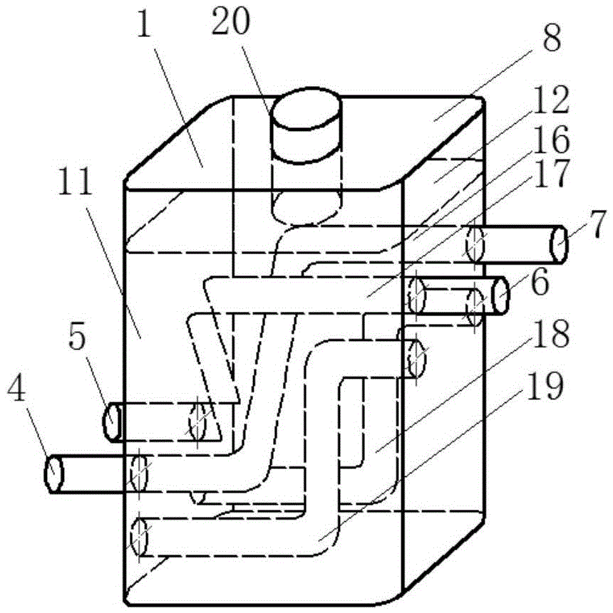
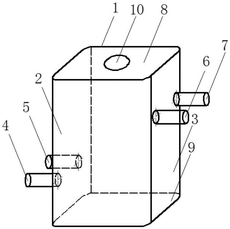
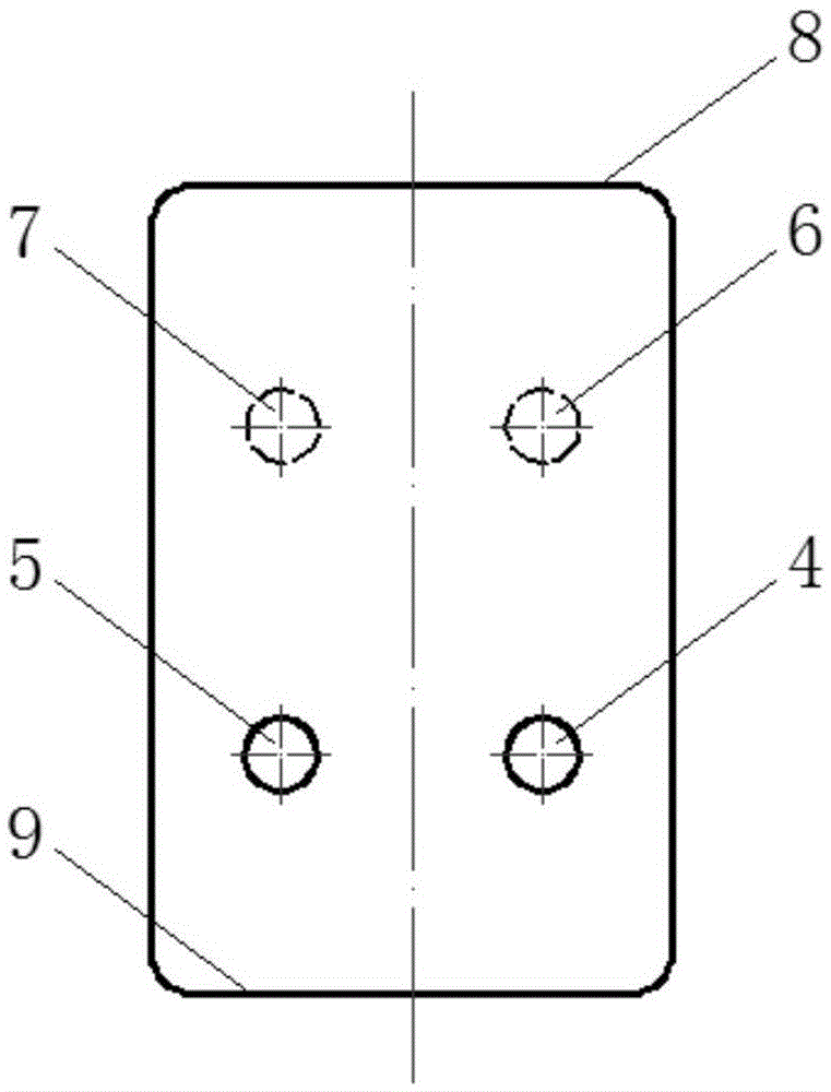

Image

  • Pressure energy recovery device based on reciprocating liquid switches
  • Pressure energy recovery device based on reciprocating liquid switches
  • Pressure energy recovery device based on reciprocating liquid switches

Examples


Embodiment Construction

[0031] In order to make the purpose, technical solutions and advantages of the embodiments of the present invention clearer, the technical solutions in the embodiments of the present invention will be clearly and completely described below in conjunction with the drawings in the embodiments of the present invention. Obviously, the described embodiments It is a part of embodiments of the present invention, but not all embodiments. Based on the embodiments of the present invention, all other embodiments obtained by persons of ordinary skill in the art without making creative efforts belong to the protection scope of the present invention.

[0032] In describing the present invention, it is to be understood that the terms "upper", "lower", "inner", "outer", "top", "bottom", "left", "right" etc. indicate an orientation or position The relationship is based on the orientation or positional relationship shown in the drawings, and is only for the convenience of describing the present...


PUM


Abstract

The invention relates to the technical field of liquid pressure energy recovery, and discloses a pressure energy recovery device based on reciprocating liquid switches. The pressure energy recovery device comprises a first switch and a second switch which are connected by a pressure exchange pipeline set, wherein the first switch and the second switch have the same structure, and respectively comprise a cylinder body and an inner core; and the inner core is assembled in the cylinder body, and can reciprocate between the initial position and end position. The switching of the positions of the inner core is implemented to circularly adjust the type of liquid introduced into the pressure exchange pipeline set, thereby achieving continuous transmission and recovery of the liquid pressure energy. The pressure energy recovery device has the advantages of simple and compact structure, wide throughput range, high adaptability, controllable pressure recovery process, low pressure loss of the liquid passing through the recovery device, and high pressure energy recovery efficiency. Besides, the liquid blending of the pressure energy recovery device occurs in the channel, pressure exchange pipeline set and other pipelines in the inner cores of the liquid switches, with low blending rate.

Description

technical field [0001] The invention relates to the technical field of liquid pressure energy recovery, in particular to a pressure energy recovery device based on a reciprocating liquid switch. Background technique [0002] In chemical fields such as membrane seawater desalination and synthetic ammonia, there is often the phenomenon that high-pressure liquid is directly discharged or directly discharged after the pressure value is reduced to the allowable pressure value through a pressure reducing valve. There is no reasonable Using the pressure energy of high-pressure liquid will cause huge waste. For example, in the process of membrane reverse osmosis seawater desalination, its operating pressure is between 6 and 7 MPa, and the pressure of concentrated brine discharged from the membrane module after separating fresh water is still as high as 5 ~6.5MPa. According to statistics, if the pressure of concentrated brine can be released directly, the loss caused will account for...

Claims


Application Information

Patent Timeline
IPC IPC(8): C02F1/44B01D61/06C02F103/08
CPCB01D61/06C02F1/441C02F2103/08
Inventor 刘中良刘宁李艳霞侯晓煌
Owner BEIJING UNIV OF TECH
Learn More