Foam two-sided adhesive tape

A double-sided adhesive tape and foam technology, applied in the field of foam double-sided adhesive tape, can solve the problems of insufficient shock resistance, low adhesive performance, and insufficient strength, etc., to avoid early decomposition, excellent mechanical properties, and cellular structure regular effect

Active Publication Date: 2016-05-04
NINGBO JIXIANG PLASTIC PROD CO LTD
View PDF5 Cites 13 Cited by
  • Summary
  • Abstract
  • Description
  • Claims
  • Application Information

AI Technical Summary

Problems solved by technology

However, with the development of science and technology and industry, the requirements for the use of tapes in manufacturing and daily life are getting higher and higher. The use of traditional PU foam-based foam tapes in some specific areas is limited, such as thicker Large, not strong enough, not high in adhesive performance, not good enough in shock resistance, not suitable for use in some precision electronics industries and other fields

Method used


Image

  • Foam two-sided adhesive tape
  • Foam two-sided adhesive tape
  • Foam two-sided adhesive tape

Examples


Embodiment 1

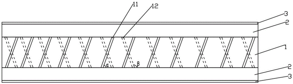
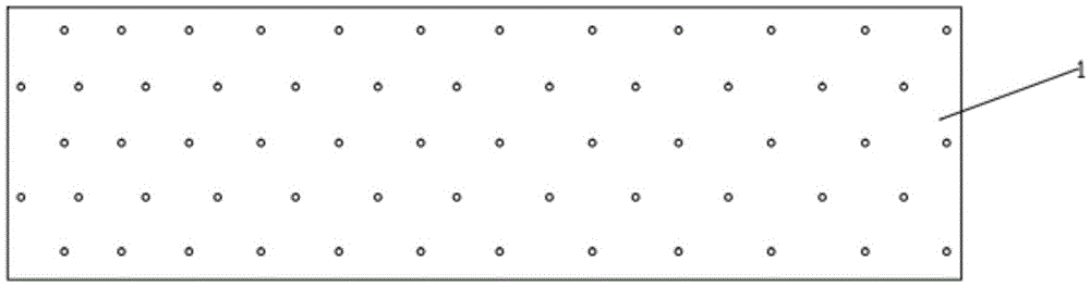
[0042] An inclined longitudinal through hole is provided between the upper surface and the lower surface of the foam substrate, the diameter of the longitudinal through hole is 220 μm, and the density on the surface of the foam substrate is 5 pieces / mm 2 . The longitudinal through hole includes longitudinal through hole I11 and longitudinal through hole II12, the angle between the longitudinal through hole I11 and the side of the lower surface of the foam substrate is α, and α is 25°, and the angle between the longitudinal through hole II12 and the side of the lower surface of the foam substrate The included angle is β, and β is 155°.

[0043] The foam substrate includes the following components in parts by weight:

[0044] 100 parts of PMMA,

[0045] 28 parts polyurethane,

[0046] 18 parts of fluorine rubber,

[0047] Light stabilizer UV-329 1.5 parts,

[0048] Mesoporous Nano TiO 2 5 copies,

[0049] Foaming agent 20 parts.

[0050] Wherein, the foaming agent is a c...

Embodiment 2

[0052] The difference from Example 1 is that,

[0053] The foam substrate includes the following components in parts by weight:

[0054] 100 parts of PMMA,

[0055] 30 parts of polyurethane,

[0056] 20 parts of fluorine rubber,

[0057] Light stabilizer GW-540 2.5 parts,

[0058] Mesoporous Nano TiO Modified by Silane Coupling Agent 2 8 servings,

[0059] Foaming agent 25 parts.

[0060] Wherein, the foaming agent is a composite powder of rare earth, sodium bicarbonate and azodicarbonamide with a weight ratio of 5:6:8.

Embodiment 3

[0062] The difference from Example 1 is that,

[0063] The foam substrate includes the following components in parts by weight:

[0064] 100 parts of PMMA,

[0065] 35 parts of polyurethane,

[0066] 23 parts of fluorine rubber,

[0067] Light stabilizer antioxidant 10103.2 parts,

[0068] Mesoporous Nano TiO Modified by Titanate Coupling Agent 2 11 copies,

[0069] 30 parts of foaming agent.

[0070] Wherein, the blowing agent is a composite powder of rare earth, sodium bicarbonate and azodicarbonamide with a weight ratio of 5:7:10.


PUM

PropertyMeasurementUnit
diameteraaaaaaaaaa
diameteraaaaaaaaaa
diameteraaaaaaaaaa

Abstract

The invention relates to a foam two-sided adhesive tape, which belongs to the technical field of an adhesive tape. The foam two-sided adhesive tape comprises a foam basal plate, an adhesive coating and a release film, wherein longitudinal through holes are formed between the upper surface and the lower surface of the foam basal plate, the foam basal plate comprises the following components in parts by weight: 100 parts of PMMA, 28 to 35 parts of polyurethane, 18 to 23 parts of fluorine rubber, 1.5 to 3.2 parts of light stabilizer, 5 to 11 parts of mesoporous nano TiO2 and 20 to 30 parts of foaming agents. The longitudinal through holes are formed in the foam basal plate, so that adhesive forms a complete lattice system, the connection performance of the adhesive tape is improved, and the connected object is more stable and reliable. The foam basal plate which is light in weight, good in shock resistance and excellent mechanical performance is adopted as the base material of the adhesive tape, so that the prepared adhesive tape is high in strength, good in flexibility, high in impact resistance and applicable to the manufacturing of more precise instruments and equipment.

Description

technical field [0001] The invention belongs to the technical field of adhesive tapes and relates to a foam double-sided adhesive tape. Background technique [0002] Foam tape is made of foam as the base material, coated with solvent-based (or hot-melt) pressure-sensitive adhesive on one or both sides and then coated with release paper. It has excellent sealing performance, compression deformation resistance and long-lasting Excellent resilience can avoid gas release and atomization, and can ensure long-term shockproof protection for accessories. It can be used for the bonding of substrates such as curved surfaces, rough surfaces and smooth surfaces, and as time goes on, the contact area between the foam tape and the substrate to be bonded will become larger, and the bonding performance will not decrease too much; it has slow Rebound characteristics, deformation recovers slowly over time, good impact resistance; lower density, which can save costs. The base materials of fo...

Claims


Application Information

Patent Timeline
Patent Type & Authority Applications(China)
IPC IPC(8): C09J7/02C08J9/08C08J9/10C08L33/12C08L75/04C08L27/12C08K13/06C08K9/06C08K9/04C08K7/24
CPCC08J9/08C08J9/103C08J2203/02C08J2203/04C08J2203/20C08L33/12C08L2201/08C08L2203/14C08L2205/03C09J7/245C09J7/26C09J2301/124C09J2301/18C09J2427/006C09J2433/006C09J2475/006C08L75/04C08L27/12C08K13/06C08K9/06C08K9/04C08K7/24
Inventor 洪连伟李宣瑾
Owner NINGBO JIXIANG PLASTIC PROD CO LTD
Why Eureka
Try Eureka