a heat exchanger

A heat exchanger, rectangular technology, applied in the field of new heat exchangers, can solve the problems of uneven air scouring of the heating surface, affecting the wide use of the heating surface, and limited space for expansion, achieving ideal heat exchange effect and reducing investment costs. , the effect of reducing the heating area

Inactive Publication Date: 2017-12-19
SHANGHAI YINGUO THERMAL ENERGY EQUIP
View PDF6 Cites 0 Cited by
  • Summary
  • Abstract
  • Description
  • Claims
  • Application Information

AI Technical Summary

Problems solved by technology

[0002] At present, the heating surface of spiral finned tubes is widely used in the field of heat exchangers or radiators. The heating surfaces of spiral finned tubes in heat exchangers can be arranged in parallel or staggered arrangement. The staggered arrangement of tubes has the advantages of good heat transfer effect and small layout space requirements, but no matter how it is arranged, it will cause dust accumulation and clogging. If the heating surface of the spiral fin tube should improve the influence of ash accumulation and clogging, The fin pitch of the spiral fin must be increased, but affected by the elongation of the material and the spiral winding process, the space for increasing the fin height and pitch is relatively limited, which affects the wide range of the heating surface. use
In addition, the heating surface of H-shaped finned tubes is also widely used in the fields of waste heat recovery devices in power plants, and its arrangement is generally arranged in a row. Compared with spiral finned tubes, the phenomenon of ash accumulation and clogging is improved. But the fly in the ointment is that the heat transfer effect is very inferior to that of the staggered arrangement. Moreover, due to the special shape of the H-shaped finned tube, it has caused certain difficulties for the majority of designers in the design and research of its staggered arrangement. Obstacles, generally arranged in a staggered manner such as Figure 4 As shown, the distance between L1 and L2 is not equal, which causes the air to scour the heating surface unevenly on the flow section

Method used


Image

  • a heat exchanger
  • a heat exchanger
  • a heat exchanger

Examples


Embodiment Construction

[0025] In order to have a further understanding and understanding of the structural features of the present invention and the effects achieved, the preferred embodiments and accompanying drawings are used in conjunction with detailed descriptions, and the descriptions are as follows:

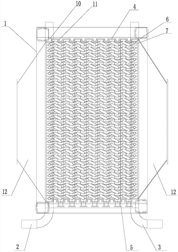
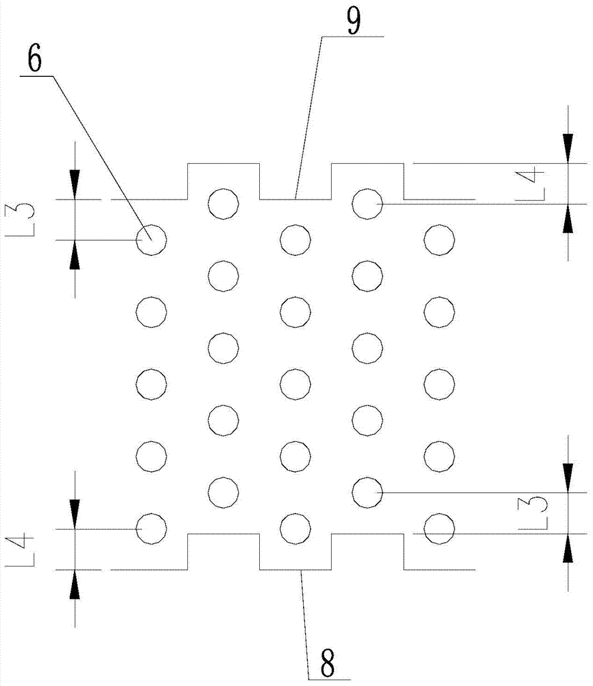
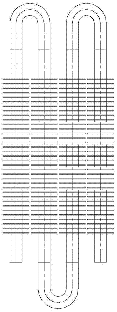
[0026] see Figure 1-Figure 3 As shown, a new type of heat exchanger includes a frame 1, an inlet header 2, an outlet header 3, a rectangular wave-shaped upper guard 4, a rectangular wave-shaped lower guard 5 and several serpentine tubes, an inlet header 2 And the outlet header 3 is vertically arranged on both sides of the frame, the rectangular wave upper guard plate 4 and the rectangular wave lower guard plate 5 are arranged on the upper and lower ends of the frame 1, and the wave crest of the rectangular wave upper guard plate 4 is the same as the rectangular wave. The wave valleys of the lower guard plate 5 are arranged vertically correspondingly. During installation, the rectangular wave lo...


PUM


Abstract

The invention provides a novel heat exchanger. The heat exchanger comprises a framework, wherein an inlet header and an outlet header are vertically arranged on the two sides of the framework; a rectangular waved upper protective plate and a rectangular waved lower protective plate are arranged at the upper end and the lower end of the inner part of the framework; peaks of the rectangular waved upper protective plate are perpendicular to and correspond to troughs of the rectangular waved lower protective plate; a plurality of coiled pipes are arranged between the rectangular waved upper protective plate and the rectangular waved lower protective plate; each coiled pipe is formed by connecting a plurality of finned tubes end to end, and each finned tube comprises a base tube and a fin; and the plurality of coiled pipes are parallel to one another and sequentially arranged side by side in the lengthwise direction of the base tubes, the two adjacent base tubes on each coiled pipe are staggered, center lines of two adjacent rows of base tubes and center lines of troughs and peaks of the rectangular waved upper and lower protective plates are the same, and a distance from a center line of the head and tail base tubes of two adjacent rows of base tubes to the edge line of the rectangular waved upper protective plate is equal to that from the center line of the head and tail base tubes of the two adjacent rows of base tubes to the edge line of the rectangular waved lower protective plate. The novel heat exchanger has the beneficial effects that the dust deposition possibility is low and heat transfer is improved.

Description

technical field [0001] The invention relates to the technical field of heat exchangers, in particular to a novel heat exchanger. Background technique [0002] At present, the heating surface of the spiral finned tube is widely used in the field of heat exchangers or radiators. The heating surface of the spiral finned tube in the heat exchanger can be arranged in series or staggered. The staggered arrangement of the tubes has the advantages of good heat transfer effect and small layout space requirements, but no matter how it is arranged, it will cause the phenomenon of fouling and fouling. It is necessary to increase the fin pitch of the spiral fins, but due to the influence of the material elongation and the spiral winding process, the space for the height and pitch of the fins to be increased is relatively limited, which affects the wide range of such heating surfaces. use. In addition, the H-finned tube heating surface has also been widely used in power plant waste heat...

Claims


Application Information

Patent Timeline
Patent Type & Authority Patents(China)
IPC IPC(8): F28D7/08F28F9/00F28F1/12
CPCF28D7/082F28F1/12F28F9/00F28F9/001
Inventor 谢岩周群英
Owner SHANGHAI YINGUO THERMAL ENERGY EQUIP
Why Eureka
Try Eureka