A Lightweight Infrared Gun Sight

An infrared gun and infrared lens technology, applied in the field of light infrared gun sights, can solve the problems of wrench slippage, low accuracy of repeated clamping, complicated and laborious operation, etc. The effect of the anti-loosening effect

Active Publication Date: 2017-08-11
HEBEI HANGUANG HEAVY IND
View PDF7 Cites 0 Cited by
  • Summary
  • Abstract
  • Description
  • Claims
  • Application Information

AI Technical Summary

Problems solved by technology

[0002] At present, there are many special parts for infrared gun sights on the market, and some are equipped with laser range finders, resulting in heavy weight and high cost;
[0003] The existing infrared gun sights are suitable for fewer firearms, the shooting table is very simple, and the shooting accuracy is not high;
[0004] The locking operation of the connection seat of the conventional infrared gun sight is complicated and laborious, and the wrench needs to be pulled multiple times, the wrench may slip, and the installation is inconvenient; and the repeatability of the card is low, which affects the shooting accuracy of the infrared gun sight;
[0005] Conventional infrared gun sights have no shock-absorbing measures. When the infrared gun sights are hit by multiple shots, firstly, the lenses in the infrared objective lens and eyepiece will have glass chipping or even glass shattering; secondly, the domestic uncooled infrared detectors will be impacted When there is a bad element, which will affect the image observation, firstly, it will cause the fixed position to be loose, which will cause the infrared detection to move or tilt, resulting in a serious zero position shift.
Moreover, it will cause damage to the infrared detector and processing circuit after being loose.

Method used


Image

  • A Lightweight Infrared Gun Sight
  • A Lightweight Infrared Gun Sight
  • A Lightweight Infrared Gun Sight

Examples


Embodiment Construction

[0062] The present invention will be described in detail below with reference to the drawings and embodiments.

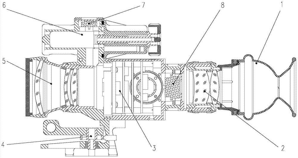
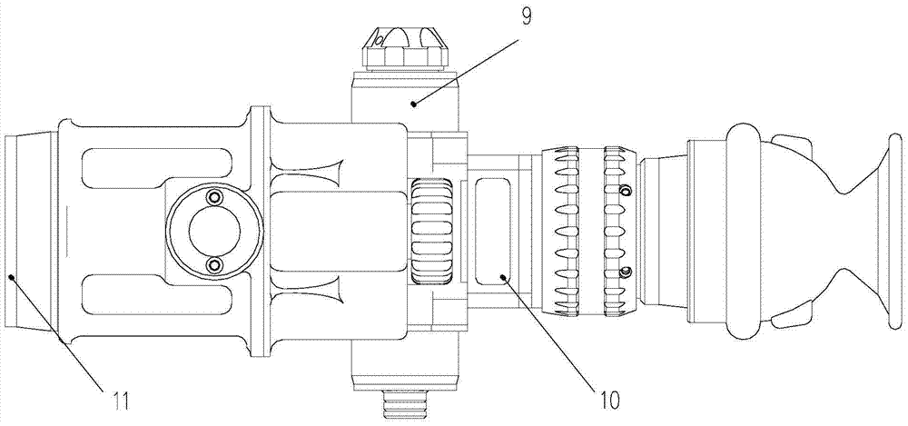
[0063] The invention provides a light infrared gunsight, see attached figure 1 , 2 , Including: light-shielding goggles 1, monocular assembly 2, infrared detector assembly 3, mirror gun connection base assembly 4, athermal infrared lens assembly 5, battery housing assembly 6, mounting base 65, switch / calibration button 7, OLED display 8. Housing assembly 9, transition frame 10 and lens cover 11;

[0064] The light-shielding goggles 1 is a funnel-shaped purchased part, the material is rubber, and the light-blocking sheet is provided at the smallest diameter of the funnel-shaped structure. When the funnel-shaped structure is axially compressed, the light-blocking sheet is automatically opened;

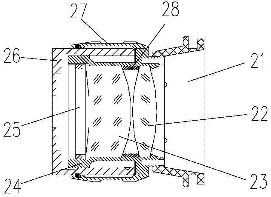
[0065] See attached image 3 , The monocular assembly 2 includes: an eyecup interface 21, a first eyepiece 23, a second eyepiece 22, a monocular inner tube 24, a monocular pressure r...


PUM


Abstract

The invention discloses a light infrared gun sight and belongs to the technical field of optical instruments. The light infrared gun sight comprises a simple ocular assembly, an infrared detector assembly, a sight-gun connecting base assembly, an athermalization infrared lens assembly, a battery assembly, an installation base, a switch / correction button, an organic light emitting diode (OLED) display and a shell assembly. One end of the sight-gun connecting base assembly is installed on a rifle, and the other end of the sight-gun connecting base assembly is connected with the bottom of the installation base. The top of the installation base is in butt joint with the battery assembly. The athermalization infrared lens assembly and the shell assembly are installed at the two ends of the installation base respectively. The infrared detector assembly is fixed in the shell assembly. The simple ocular assembly is connected with the shell assembly. The OLED display is fixed between the infrared detector assembly and the simple ocular assembly. The switch / correction button is installed on the top surface of the installation base and electrically connected with the battery assembly and the infrared detector assembly. A single personnel target which is about 500 m away can be observed and sighted through the light infrared gun sight, and the light infrared gun sight can work around the clock in all weathers.

Description

Technical field [0001] The invention belongs to the technical field of optical instruments, and specifically relates to a light infrared gunsight. Background technique [0002] At present, there are many special parts for infrared riflescopes on the market, and some are equipped with laser rangefinders, which results in heavier weight and very high cost; [0003] The existing infrared riflescopes are suitable for fewer firearms, the shooting table is very simple, and the shooting accuracy is not high; [0004] Conventional infrared riflescope connecting seat locking operation is complicated and laborious, and the wrench needs to be pulled many times, the wrench may slip, and the installation is inconvenient; and the accuracy of repeated mounting is low, which affects the shooting accuracy of the infrared riflescope; [0005] Conventional infrared riflescopes have no shock absorption measures. When the infrared riflescopes are impacted by multiple shots, firstly the glass in the infrar...

Claims


Application Information

Patent Timeline
Patent Type & Authority Patents(China)
IPC IPC(8): F41G1/36F41G1/46
CPCF41G1/36F41G1/46
Inventor 马萄李晓雷薛敏张溪周立媛路晓伟
Owner HEBEI HANGUANG HEAVY IND
Why Eureka
Try Eureka