Ultrasonic coating detection method

A detection method, ultrasonic technology, applied in the use of sound waves/ultrasonic waves/infrasonic waves to analyze solids, use sound waves/ultrasonic waves/infrasonic waves for material analysis, and measurement devices, etc., which can solve the problem of not providing numerical standards for ultrasonic detection, numerical judgment standards, and quantification Detect problems such as the lack of accurate setting standards, so as to improve the measurement accuracy and efficiency and ensure the quality of coating bonding

Active Publication Date: 2016-05-04
CHINA HANGFA SOUTH IND CO LTD
View PDF5 Cites 13 Cited by
  • Summary
  • Abstract
  • Description
  • Claims
  • Application Information

AI Technical Summary

Problems solved by technology

When this method detects the plate, the setting of the focal length is very random, that is, observe the wave height of the reflected echo on the upper surface of the metal plate until the maximum value appears, but the maximum value should appear at the depth of the defect, but the depth of the defect is not fixed, so The above prior art can only be used in occasions where there are many and obvious defects and the general quality requirements are not high, and there is no precise setting standard for the quantitative detection of aero-engine coatings that require extremely high quality inspection, that is, the prior art No numerical standard for judging ultrasonic testing is provided
Similarly, although the gap-free ultrasonic detection method disclosed in Chinese patent application CN201310472205.5 is confirmed by metallographic analysis, it also provides qualitative analysis, and there is no quantitative numerical judgment standard for reference

Method used


Image

  • Ultrasonic coating detection method
  • Ultrasonic coating detection method
  • Ultrasonic coating detection method

Examples


Embodiment Construction

[0022] In order to have a clearer understanding of the technical features, purposes and effects of the present invention, the specific implementation manners of the present invention will now be described with reference to the accompanying drawings. Wherein, the same parts adopt the same reference numerals.

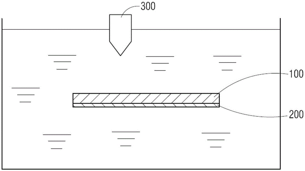
[0023] figure 1 Shown is a schematic diagram of the detection layout of an ultrasonic coating detection method according to a specific embodiment of the present invention. As shown in the figure, the ultrasonic coating detection method is used to utilize ultrasonic detection equipment (only ultrasonic detection The ultrasonic probe 300 of the equipment) detects the coating 200 on the substrate 100 of the parts of the aero-engine, wherein the substrate material is a nickel-based superalloy steel, and the coating is preferably an AlSi6% alloy material (Al94%+Si6% alloy).

[0024] As shown in the figure, the basic principle of the detection method of the present invention ...


PUM

PropertyMeasurementUnit
lengthaaaaaaaaaa
thicknessaaaaaaaaaa
heightaaaaaaaaaa

Abstract

An ultrasonic coating detection method is used to detect the coating on the matrix of parts of aero-engine. The method comprises the following steps: horizontally arranging a matrix in a water tank, wherein the coating on the matrix is face-down; adjusting the focus of a probe to make the focus fall on the bottom surface of the matrix; through a pre-fitted function curve of ratio of reflection echo signal height of ultraviolet detection equipment to defect of combination between coating and matrix, filling values into the curve to calculate the ratio, and judging the quality is qualified or not. Through the optimized ultrasonic coating detection, a set of standard values for ultrasonic detection is established. The detection can be carried out automatically and digitally. The measurement precision and efficiency are improved. The method can be applied to the non-destructive detection of aero-engines to ensure the quality of coating bonding.

Description

technical field [0001] The invention relates to an aero-engine coating detection technology, in particular to a method for using ultrasonic waves to detect coatings on components of an aero-engine, in particular to an ultrasonic coating detection method. Background technique [0002] In aero-engines, some parts need to be sprayed with wear sealing coating of AlSi6% material (Al94%+Si6% alloy) to ensure the sealing of these parts. Existing aero-engine manufacturers' inspection of the coating quality of such parts is limited to visual inspection of its apparent quality, while the bonding quality of the coating and the substrate can only be guaranteed by the process without any non-destructive testing methods. In this way, once If the spraying process is out of control, it may lead to the failure of parts with coating peeling off due to poor coating bonding quality, which will endanger the safety of the engine. [0003] The bonding defect of sprayed parts is generally the defe...

Claims


Application Information

Patent Timeline
Patent Type & Authority Applications(China)
IPC IPC(8): G01N29/04G01N29/06
CPCG01N29/043G01N29/069G01N2291/0289
Inventor 石剑桂咏梅吕健
Owner CHINA HANGFA SOUTH IND CO LTD
Why Eureka
Try Eureka