Quick testing method for radiation characteristic of array antenna

A technology of radiation characteristics and array antennas, applied in the field of array antennas, can solve the problems of slow test speed, high test cost, high calibration and maintenance costs, and achieve high accuracy of results, comprehensive test results, and small footprint

Active Publication Date: 2016-05-04
SHIJIAZHUANG SHILIANDA TECH
View PDF7 Cites 30 Cited by
  • Summary
  • Abstract
  • Description
  • Claims
  • Application Information

AI Technical Summary

Problems solved by technology

The algorithm of the near-field measurement method is complex, and the multi-probe technology brings a series of problems such as the consistency of the probes and position correction. In order to reduce the mutual interference between the probes, the test system cannot be too small, or the number of probes cannot be too many
Therefore, the composition of the near-field m

Method used


Image

  • Quick testing method for radiation characteristic of array antenna
  • Quick testing method for radiation characteristic of array antenna
  • Quick testing method for radiation characteristic of array antenna

Examples


Embodiment 1

[0083] The method of the invention is used to measure a pair of single-port antennas, the antenna is 1.5 meters long, the frequency of the antenna to be tested is 1710-2170 MHz, and the design gain is 5 degrees for the main lobe width and 2 degrees for the main lobe direction.

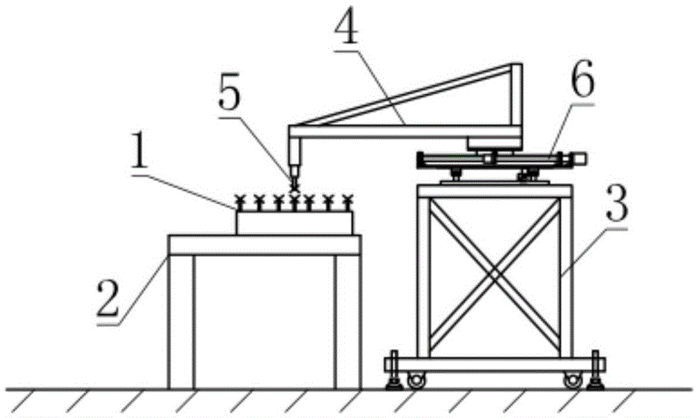
[0084] In this embodiment, the probe adopts one-dimensional linear moving scanning. The one-dimensional linear movement of the probe is along the central axis of the antenna to be tested, and the scanning range of the probe is the axial length of the antenna to be tested. The measurement sampling interval of the probe is 50mm, and the total number of measurement sampling points is 30.

[0085] The specific measurement steps are:

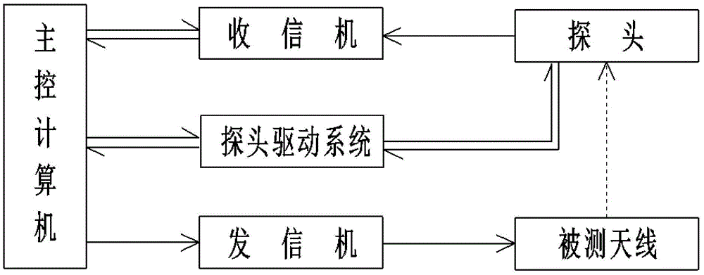
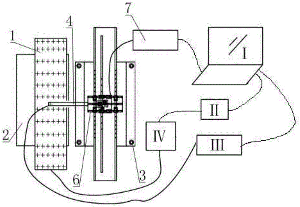
[0086] A. Driven by the main control computer, the transceiver sends the transmission signal to the antenna under test, and the probe moves along the central axis near the antenna opening, and receives the signal transmitted by the antenna under test at the measurement point...

Embodiment 2

[0099] The method of the present invention is used to measure a pair of two-port antenna, the antenna is 1.6 meters long and 0.6 m wide.

[0100] In this embodiment, the probe adopts two-dimensional grid moving scanning. The two-dimensional grid movement of the probe is to perform a two-dimensional scan on the main radiation port of the array antenna, and start a turn-back scan from an edge point of the array antenna. Measurement sampling interval along the antenna length (d y ) is 40mm, and the measurement sampling interval in the antenna width direction (d x ) is 0.3m, and the total number of measurement sampling points is 2*40.

[0101] The specific measurement steps are:

[0102] A. Driven by the main control computer, the transceiver sends the transmission signal to the antenna under test, and the probe moves along the central axis near the antenna opening, and receives the signal transmitted by the antenna under test at the measurement point, and passes through the re...


PUM


Abstract

The invention provides a quick testing method for the radiation characteristic of an array antenna. In a non-darkroom environment, a transceiver is used for emitting a signal to the antenna to be tested, a probe moving according to a track is used for receiving the signal and transmitting the signal back to the transceiver, a main control computer is used for calculating an output port surface near field value, a directional diagram of the array antenna to be tested is synthesized according to the output port surface near field value, and then a parameter value of the radiation characteristic of the array antenna is obtained. The method has no special requirement for the testing environment and is not limited by site size, weather and the like, a strict shield chamber is not needed, testing can be carried out in the production environment or the research and development environment of the antenna, testing speed and efficiency are high, the testing devices occupy a small area, testing can be carried out anytime conveniently and rapidly, the testing result is comprehensive and accurate, and the method is particularly suitable for quick detection of antenna products on a production line and being used for primary detection of the antenna during product research and development.

Description

technical field [0001] The invention relates to a method for quickly measuring radiation characteristics of an array antenna, belonging to the technical field of array antennas. Background technique [0002] With the development of wireless communication technologies such as mobile communication, antenna technology has also developed rapidly. Among them, the array antenna has been more and more widely used due to its diversity of feeding excitation sources, flexibility of scanning form, conformal design and intelligent management, and has become the largest installed capacity in the mobile communication cellular network. kind of antenna. In my country, due to considerations of capital and land, environmental protection, construction period, etc., multiple cellular systems of multiple operators are usually set up on the same base station, multiple cellular systems share a tower, and each cellular system When multiple antennas are configured, the same-site interference proble...

Claims


Application Information

Patent Timeline
IPC IPC(8): G01R29/10
CPCG01R29/10
Inventor 邓晖卢童陈东刘山虎
Owner SHIJIAZHUANG SHILIANDA TECH
Why Eureka
Try Eureka