Object positioning system based on position and attitude of airborne photoelectric gondola

A photoelectric pod and target positioning technology, applied in satellite radio beacon positioning system, radio wave measurement system, measurement device, etc., can solve the difficulty of ensuring real-time position and attitude information, the selection of interfaces or the difficulty of obtaining data formats , difficult to achieve high precision and other problems

Inactive Publication Date: 2016-05-04
DALIAN MARITIME UNIVERSITY
View PDF5 Cites 37 Cited by
  • Summary
  • Abstract
  • Description
  • Claims
  • Application Information

AI Technical Summary

Problems solved by technology

[0005] The navigation information comes from the aircraft carrier. Since the navigation system is a special device, it is difficult to select the interface or obtain the data format.
[0006] Because the position and attitude information of the photoelectric pod is directly related to the target positioning, but the navigation information of the aircraft carrier is introduced into the positioning calculation. Although the photoelectric pod is installed on the aircraft carrier, the position and attitude information of the two are not synchronized. , it is difficult to guarantee the real-time performance of position and attitude information
In addition, the acquisition of the position and attitude information of the aircraft carrier itself cannot be achieved in real time, and accurate target positioning information cannot be calcu

Method used


Image

  • Object positioning system based on position and attitude of airborne photoelectric gondola
  • Object positioning system based on position and attitude of airborne photoelectric gondola
  • Object positioning system based on position and attitude of airborne photoelectric gondola

Examples


Embodiment Construction

[0052] In order to make the purpose, technical solutions and advantages of the embodiments of the present invention more clear, the technical solutions in the embodiments of the present invention are clearly and completely described below in conjunction with the drawings in the embodiments of the present invention:

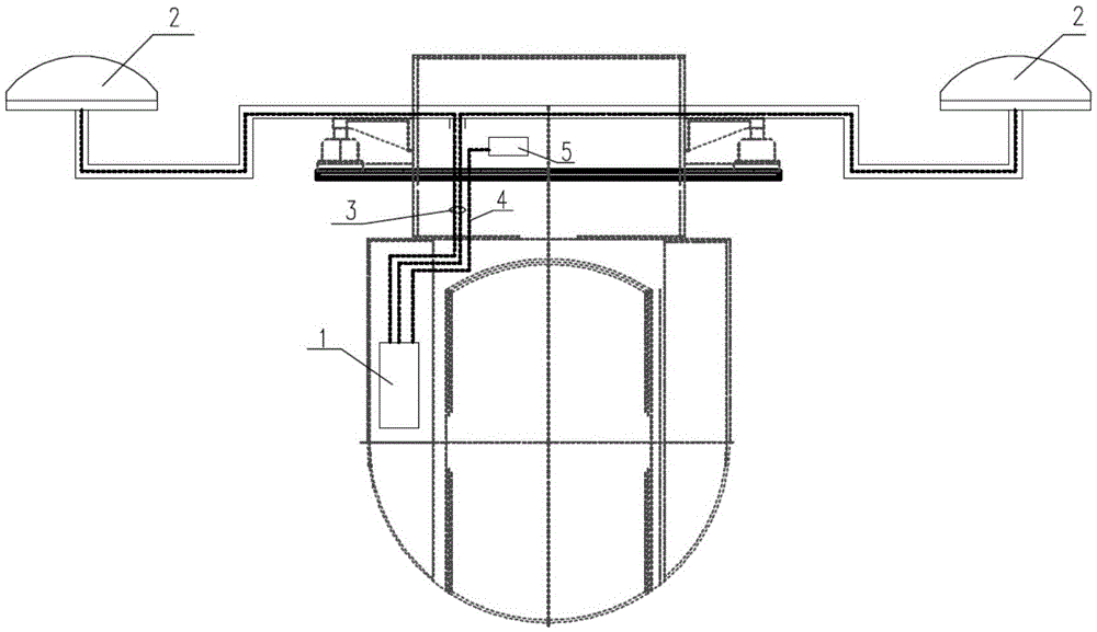
[0053] figure 1 The installation position of the position and attitude measuring equipment of the present invention on the photoelectric pod is shown. The position and attitude measurement equipment includes 1 measuring instrument, 2 dual positioning antennas, 3 antenna feeders, 4 data lines and 5 RS422 interfaces.

[0054] Meter 1 is mounted on figure 1 The inner shell wall of the photoelectric pod shown in the photoelectric pod must be installed without any contact with the pitching frame of the photoelectric pod stable platform, and does not hinder the angle adjustment of the pitching frame. Photoelectric pods with different internal structures can be adjusted...


PUM


Abstract

The invention discloses an object positioning system based on the position and attitude of an airborne photoelectric gondola, and the system is arranged in the airborne photoelectric gondola. The system includes a dynamic inclination angle obtaining module, a positioning module and a processing module, wherein the dynamic inclination angle obtaining module obtains the pitch angle theta and roll angle gamma information of the airborne photoelectric gondola; the processing module obtains the longitude Bc, the latitude Lc, the height Hc and the yaw angle phi of the airborne photoelectric gondola; and according to the longitude, latitude and height of the airborne photoelectric gondola as well as the longitude Bm, latitude Lm and height Hm of a ground reference point, the processing module converts a geodetic right-angle coordinate system into an ENU coordinate system (Xwk, Ywk, Zwk); and according to an object image obtained by the airborne photoelectric gondola, the processing module obtains the pixel coordinates (u, v) of an object in the image, a translation matrix T1 is generated by combining the focal length f of a camera of the gondola, the distance Yc of the axial center image of the gondola and the camera to the sea surface and the geodetic right-angle coordinate system (Xck, Yck, Zck) of the ground reference point, practical latitude, longitude and elevation of the object is obtained via the pixel coordinates of the object, and measurement for the object is completed.

Description

technical field [0001] The invention relates to a target positioning system based on the position and attitude information of an airborne photoelectric pod. Mainly related to patent number: G01 Measurement; Test G01S Radio Orientation; Radio Navigation; Using Radio Waves to Measure Distance or Velocity; Positioning systems; use of signals transmitted by such systems to determine position, velocity or attitude G01S19 / 38 Use of signals transmitted by satellite radio-beacon positioning systems to determine navigation schemes G01S19 / 39 Transmission of satellite radio-beacon positioning systems with time-stamped information , such as GPS [Global Positioning System], GLONASS [Global Navigation Satellite System] or GALILEOG01S19 / 42 to determine the position. Background technique [0002] With the increasing number and density of ships, aircraft and personnel at sea, the navigation environment is becoming more and more complex, and the global climate is abnormal, the probability an...

Claims


Application Information

Patent Timeline
IPC IPC(8): G01S19/53G01S19/42G01S19/47G01C21/16G01C11/00
CPCG01C11/00G01C21/165G01S19/421G01S19/47G01S19/53
Inventor 董丽丽赵明季园园李瑛许文海
Owner DALIAN MARITIME UNIVERSITY
Why Eureka
Try Eureka