Wind power generator system and fluid transportation apparatus

A technology of wind power generators and generators, which is applied in the direction of wind power generators, wind power motor combinations, electromechanical devices, etc. It can solve the problems of affecting the normal use of generators, destroying the insulation mechanism of generators, reducing the life of generators, etc., and improving the cooling effect , high use intensity, space-saving effect

Active Publication Date: 2016-05-04
XINJIANG GOLDWIND SCI & TECH
View PDF4 Cites 16 Cited by
  • Summary
  • Abstract
  • Description
  • Claims
  • Application Information

AI Technical Summary

Problems solved by technology

The moisture and salt contained in the above-mentioned multi-phase flow will cause damage to the magnetic poles of the generator, and even cause irreversible demagnetization and demagnetization, and will also damage the insulation mechanism of the generator; the solid-phase substances such as sand and dust contained in the above-mentioned multi-phase flow will enter the generator If it is damaged inside, it will cause wear to the generator, affect the normal use of the generator, and reduce the life of the generator

Method used


Image

  • Wind power generator system and fluid transportation apparatus
  • Wind power generator system and fluid transportation apparatus
  • Wind power generator system and fluid transportation apparatus

Examples


Embodiment 1

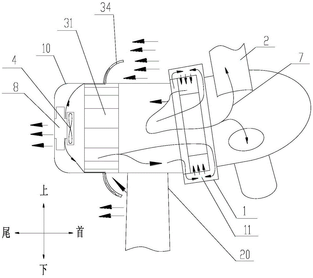
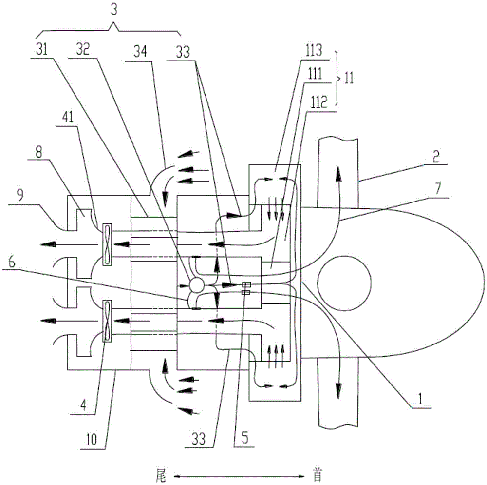
[0111] Such as figure 1 and figure 2 As shown, in the first specific embodiment, the exhaust fan 4 and the noise absorbing device 8 can be arranged at the rear of the nacelle 10 of the wind power generator system, and the above-mentioned separation device 3 can be located in the upwind direction of the exhaust fan 4 and the exhaust device 9; The exhaust fan 4 , the noise absorbing device 8 and the exhaust device 9 may communicate in sequence along the upwind direction. At the same time, the air outlet of the air exhaust device 9 can be set as flared, so as to improve the air exhaust efficiency and reduce the air exhaust noise. The air exhaust device 9 can also make the exhaust wind roughly parallel to the upwind direction and be discharged from the tail of the nacelle 10. It can be seen from fluid mechanics that the area at the tail of the nacelle 10 extending a certain distance along the upwind direction is basically a sound-absorbing zone. When the air exhaust device 9 Wh...

Embodiment 2

[0116] Please refer to Figure 12 and Figure 13 , in the second specific embodiment, the exhaust fan 4 and the noise absorbing device 8 can be arranged on the side of the nacelle 10 of the wind power generator system. At this time, the separation device 3 is in the downwind direction of the exhaust fan 4 and the exhaust device 9 The side of the nacelle 10 is relative to the upwind direction, that is, the side that is in the upwind direction, or not in the fore-and-aft direction, and specifically can be a direction perpendicular to the upwind direction. At this time, in order to avoid mutual interference between the upwind incoming flow and the exhaust of the exhaust device 9, the air inlet of the separation device 3 can be approximately perpendicular to the air outlet of the exhaust device 9, or at a predetermined angle, usually the predetermined angle is greater than 80 degrees .

[0117] It should be noted that, in this article, whenever it is mentioned that it is roughly...


PUM


Abstract

The invention provides a wind power generator system. According to the wind power generator system, multi-phase flows entering the generator can be separated to reduce moisture and impurities entering the generator so as to improve the insulating performance of the generator while a cooling effect is achieved, and to reduce abrasion for a heat exchanging surface of the internal cavity of the generator. The wind power generator system comprises the generator with a motor cavity and blades connected with the rotor of the generator; the wind power generator system also comprises a separating apparatus used for performing multi-phase flow separation for flows from a windward direction; the air inlet of the separating apparatus is used for introducing flows from the windward direction; the air outlet is communicated with the motor cavity; and the motor cavity is communicated with an exhaust fan for discharging hot air flows. The invention also provides a fluid transportation apparatus, wherein the fluid transportation apparatus comprises power equipment with an overheat cavity; the fluid transportation apparatus also comprises the separating apparatus used for performing multi-phase flow separation for flows from the windward direction; the air inlet of the separating apparatus is used for introducing flows from the windward direction; the air outlet is communicated with the overheat cavity; and the overheat cavity is also communicated with the exhaust fan for discharging hot air flows.

Description

technical field [0001] The invention relates to the field of air cooling technology, in particular to a wind power generator system and a fluid transport device. Background technique [0002] A wind turbine is a device that converts wind energy into electrical energy, mainly including components such as generators and blades. In the prior art, a permanent magnet synchronous motor is usually used as a wind power generator. Since the wind power generator is used outdoors and the natural environment is harsh, the temperature resistance of the permanent magnet of the generator is not high, and the cooling problem is particularly prominent. In order to achieve cooling of the generator while saving costs, air cooling is generally used in the prior art, that is, air in the natural environment is introduced into the air gap between the stator and the rotor of the generator for heat exchange to achieve cooling. [0003] However, the air in the natural environment is often mixed with...

Claims


Application Information

Patent Timeline
Patent Type & Authority Applications(China)
IPC IPC(8): H02K9/06H02K9/26F03D9/25
CPCH02K9/06H02K9/26F03D9/25F05B2260/96H02K5/24H02K7/1838H02K9/04Y02E10/72F03D9/28
Inventor 马盛骏马万顺
Owner XINJIANG GOLDWIND SCI & TECH
Why Eureka
Try Eureka