Fusion tapered optical fiber power beam combiner and manufacturing method thereof

A technology of a beam combiner and an optical fiber bundle, which is applied to the melting point taper type optical fiber power beam combiner and its production field, can solve the problems that the optical fiber High power output, guaranteed coupling efficiency, high brightness signal laser beam combining effect

Inactive Publication Date: 2016-05-11
NAT UNIV OF DEFENSE TECH
View PDF4 Cites 18 Cited by
  • Summary
  • Abstract
  • Description
  • Claims
  • Application Information

AI Technical Summary

Problems solved by technology

[0003] The technical problem to be solved by the present invention is: the fiber combiner made based on the traditional fus...

Method used


Image

  • Fusion tapered optical fiber power beam combiner and manufacturing method thereof
  • Fusion tapered optical fiber power beam combiner and manufacturing method thereof
  • Fusion tapered optical fiber power beam combiner and manufacturing method thereof

Examples


Embodiment 1

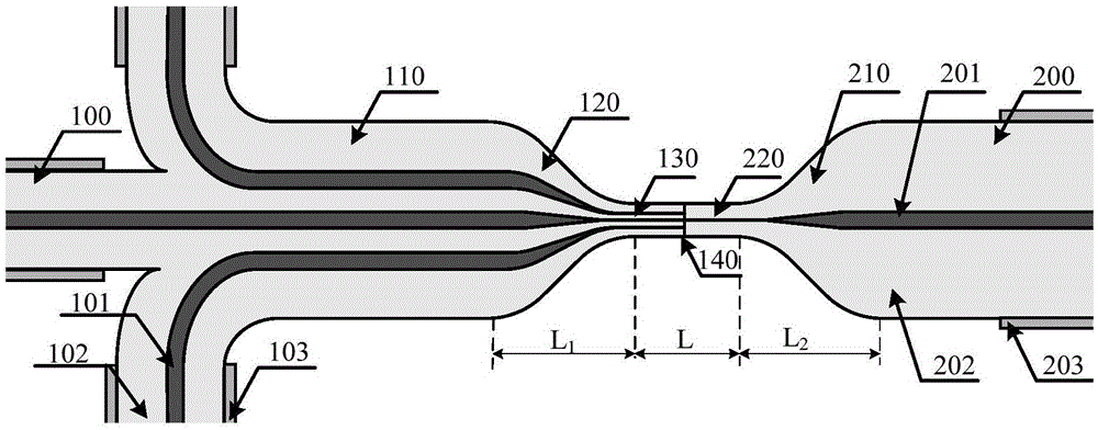
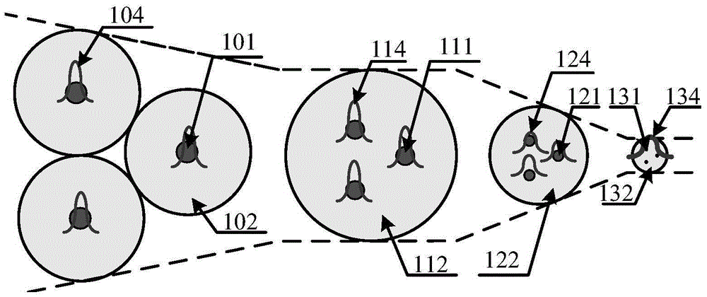
[0038] Figure 1 to Figure 3 It is an implementation process of making a 3×1 melting point tapered optical fiber power combiner by directly combining tapered tapes. During the manufacturing process, firstly, 4 cm of the middle coating layer 103 (including the outer cladding) of the three double-clad signal optical fibers 100 with core / inner cladding diameters of 15 / 130 μm were removed to expose the inner cladding 102 . Use two optical fiber clamps to hold the optical fibers on both sides of the three optical fibers with the coating layer, and then twist them one or two times in the opposite radial direction to make the three optical fibers closely fit in the area where the coating layer is stripped together, such as figure 2 The structure on the left is shown. Then put the bundled fiber bundles on the fiber optic tapering machine, use the flame to heat the stripped coating area to make them fuse with each other, and at the same time apply a pulling force in the opposite dir...

Embodiment 2

[0040] Figure 5 to Figure 6 It is the implementation process of making a 7×1 melting point tapered optical fiber power combiner by means of low refractive index glass tube grouping. During the manufacturing process, firstly, the coating layer 103 (including the outer cladding) at one end of seven double-clad signal optical fibers 100 with core / inner cladding diameters of 20 / 130 μm was removed by 4 cm to expose the inner cladding 102 . At the same time, two low-refractive index glass tubes 300 with a length of 10 cm (numerical aperture NA=0.22, inner diameter / outer diameter 800 / 1000 μm) were tapered to 400 / 500 μm in the middle section, so that the length of the cone waist was 2 cm. Then the inner claddings of the processed seven optical fibers are inserted into the low-refractive-index glass tube, so that the inner claddings are closely arranged in the tapered waist area 300 of the glass tube, such as Image 6 The structure on the left is shown. Then place the glass tube 300...


PUM


Abstract

The invention provides a fusion tapered optical fiber power beam combiner and a manufacturing method thereof. The beam combiner consists of an input signal optical fiber (100), a fused optical fiber beam (110), a tapered transition region optical fiber beam (120), a tapered homogeneity region (130), a fusion joint (140), a tapered homogeneity region output optical fiber (220), a tapered transition region output optical fiber (210) and an output doubly-clad optical fiber (200). The manufacturing method comprises the following steps: firstly fusing and tapering the input optical fiber beam to a cladding size matched with that of the output optical fiber, then performing fusion welding on the fusion tapered optical fiber beam and the output optical fiber, and finally re-tapering the fusion welding point region, thereby finishing manufacturing of the beam combiner. The beam combiner is capable of realizing high-brightness signal laser beam combination while ensuring the coupling efficiency and realizing high-power output, and has great significance for high-power laser.

Description

technical field [0001] The invention relates to the technical field of fiber lasers, in particular to a melting point tapered fiber power combiner and a manufacturing method thereof. Background technique [0002] Fiber lasers are a new generation of solid-state lasers after traditional solid-state lasers and gas lasers. They have the advantages of high conversion efficiency, good beam quality, compact structure, easy heat dissipation, and good working stability. They have been widely used in industry and national defense. At present, IPG has reported a single-mode fiber laser with an output power of 10kW. However, due to the limitations of fiber nonlinear effects and optical thermal damage, the output power of a single fiber laser cannot be increased infinitely. In order to obtain greater fiber laser output, combining multiple medium-power fiber lasers is an effective means. The combination of fiber laser is mainly divided into two ways: coherent combination and incoherent...

Claims


Application Information

Patent Timeline
IPC IPC(8): G02B6/255G02B6/25
CPCG02B6/2551G02B6/25G02B6/2553
Inventor 周旋风陈子伦王泽锋侯静奚小明雷成敏许晓军
Owner NAT UNIV OF DEFENSE TECH
Why Eureka
Try Eureka