
Schottky diode and manufacturing method thereof

A technology of Schottky diode and fabrication method, applied in semiconductor/solid-state device manufacturing, semiconductor devices, electrical components, etc., can solve the problems of inaccurate size control at the widest point of P well, decreased device stability, and inability to reduce VF, etc. , to achieve the effect of omitting the high temperature push junction process, reducing the VF, and enhancing the electron capture ability

Active Publication Date: 2016-05-11
FOUNDER MICROELECTRONICS INT
View PDF3 Cites 0 Cited by
  • Summary
  • Abstract
  • Description
  • Claims
  • Application Information

AI Technical Summary

Problems solved by technology

[0005] The purpose of the embodiments of the present invention is to provide a Schottky diode and a manufacturing method thereof, so as to solve the following problems in the manufacturing process of the Schottky diode in the prior art: when forming the P-well, high-temperature pushing junction is used, which reduces the stability of the device , and the size control of the widest part of the P-well is not precise, and the VF cannot be reduced

Method used


Image

  • Schottky diode and manufacturing method thereof
  • Schottky diode and manufacturing method thereof
  • Schottky diode and manufacturing method thereof

Examples


Embodiment Construction

[0048] The Schottky diode provided by the present invention and its manufacturing method will be described in more detail below with reference to the drawings and embodiments.

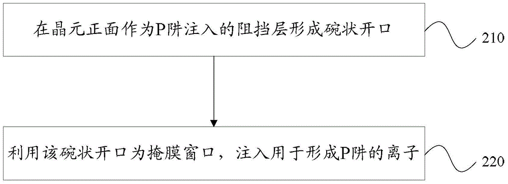
[0049] Embodiments of the present invention, such as figure 2 As shown, the manufacturing method of the Schottky diode at least includes the following steps:

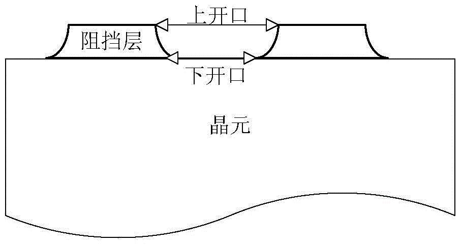
[0050] Step 210: forming a bowl-shaped opening on the front side of the wafer as a barrier layer implanted into the P well;

[0051] Among them, the wafer is the carrier for making Schottky diodes. The front side of the die refers to the side that is used to form the Schottky diode.

[0052] Step 220 : using the bowl-shaped opening as a mask window, injecting ions for forming a P well.

[0053] In the embodiment of the present invention, the self-alignment method of the bowl-shaped opening is used to inject ions for forming the P well. Because the mask window used as the P-well ion implantation is a bowl-shaped opening, the P-well can be fo...


PUM


Abstract

An embodiment of the invention discloses a Schottky diode and a manufacturing method thereof. The method comprises the following steps of forming a bowl-shaped opening on a barrier layer which is implanted as a P well on a front side of a wafer; and using the bowl-shaped opening as a mask layer window and implanting ions used for forming the P well. Because the mask layer window which is implanted as the P well ions is the bowl-shaped opening, the P well can be formed through an ion implantation technology and a high temperature knot pushing technology is omitted. Compared to the high temperature knot pushing, the ion implantation is controllable so that a size of the widest position of the formed P well is accurate and a low VF is acquired. Besides, the high temperature knot pushing technology is omitted so that stability of the schottky diode is increased. Further, a silicide is used to replace traditional polycrystalline silicon to make an induction grid. Because a barrier where metal and silicon are contacted is very low, an electron capturing capability of the induction grid to a channel formed by the P well and N+ is increased so that a grid voltage needed by inversion of the channel formed by the Schottky diode P well and the N+ is reduced and the VF is decreased.

Description

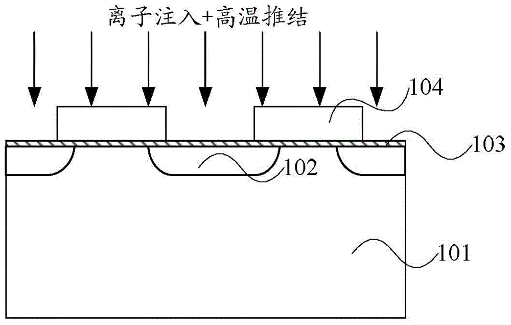
technical field [0001] The invention relates to the field of semiconductor devices and their manufacturing techniques, in particular to a Schottky diode and a manufacturing method thereof. Background technique [0002] Schottky diodes are essential supporting devices in high-frequency circuits, and are widely used in voltage regulators, rectifiers, inverters, uninterrupted power supplies (UniterruptedPowerSupply, UPS) and other circuits. [0003] In Schottky diode manufacturing technology, in order to obtain excellent electrical properties, a P well is usually used to form a protective junction to reduce the reverse leakage current of the device. Such as figure 1 As shown, it is a schematic diagram of a conventional self-aligned implant push-junction process, and a steep opening is etched on the gate region 103 as a barrier layer 104 for P-well implantation. Using the steep opening as a mask window, ion implantation is performed, and high-temperature push junction is perfo...

Claims


Application Information

Patent Timeline
Patent Type & Authority Applications(China)
IPC IPC(8): H01L29/872H01L21/329
Inventor 姜春亮何昌蔡远飞
Owner FOUNDER MICROELECTRONICS INT
Learn More