
Guide device for polycrystal ingot casting furnace

A technology of a diversion device and an ingot furnace, which is applied to the growth of polycrystalline materials, crystal growth, single crystal growth, etc., can solve the problems of supercooling, inconvenient operation of the furnace, and inability to observe the state of the ingot furnace, and achieves heat reduction. , the effect of reducing the degree of supercooling and increasing the contact area

Active Publication Date: 2016-05-25
京山新瑞达通用机器有限公司
View PDF7 Cites 0 Cited by
  • Summary
  • Abstract
  • Description
  • Claims
  • Application Information

AI Technical Summary

Problems solved by technology

In order to overcome the problems existing in the application of the flow guide device in the prior art: the carrier gas is concentratedly blown on a certain area on the surface of the liquid silicon, and the carrier gas takes away a large amount of heat from this area, causing the local supercooling of the liquid silicon in this area, which promotes The nucleation and growth of impurities in liquid silicon; the field of view leading to the ingot furnace in the diversion device is completely blocked, and the state of the ingot furnace cannot be observed through the observation window through the diversion device, which is inconvenient for the furnace operation; the crystal rod cannot It cannot be inserted into the ingot furnace through the diversion device, and the crystal growth rate is inconvenient to measure; the infrared detector cannot detect the state of the silicon material in the furnace, and the automatic crystal growth process cannot be carried out normally

Method used


Image

  • Guide device for polycrystal ingot casting furnace
  • Guide device for polycrystal ingot casting furnace
  • Guide device for polycrystal ingot casting furnace

Examples


Embodiment approach 1

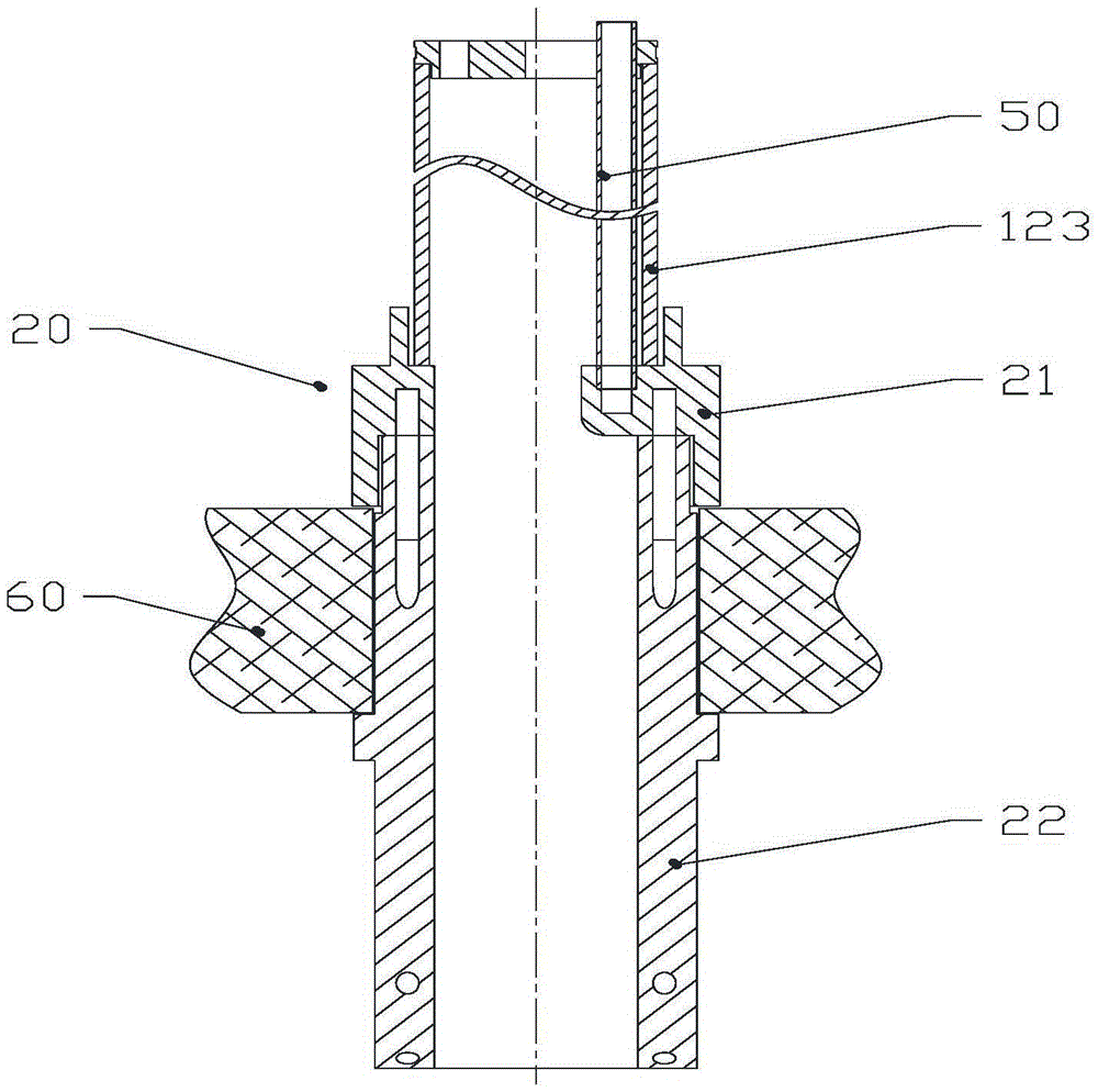
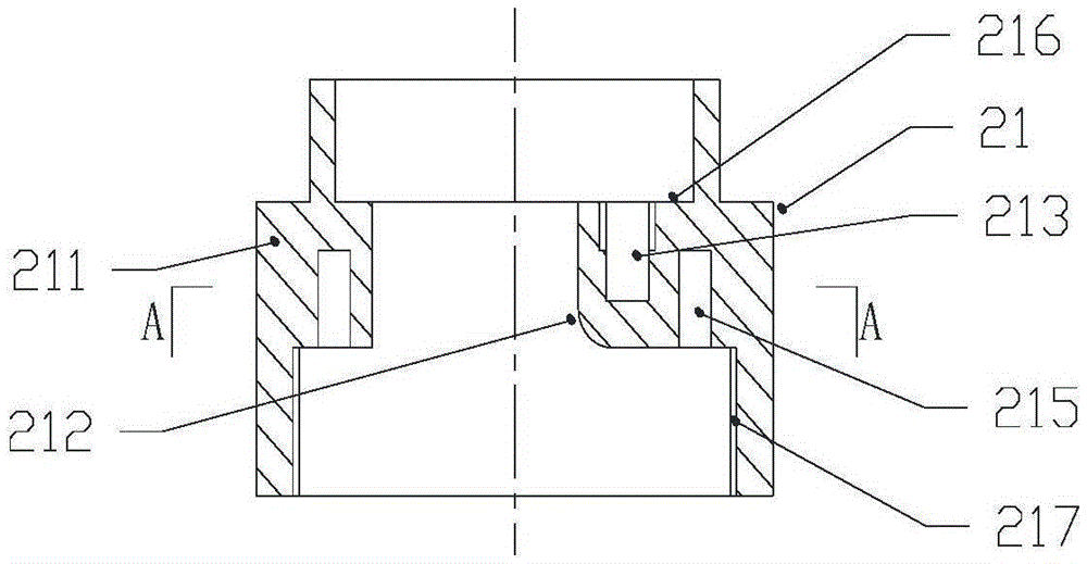
[0066] A kind of diversion device for polycrystalline ingot furnace of the present invention, such as figure 2 As shown, the flow guiding device 20 includes an adapter cylinder 21 and a flow guiding cylinder 22 . The lower end of the fitting cylinder 21 is provided with an internal thread 217 , and the upper end of the guide cylinder 22 is provided with an external thread 224 ; The middle part of the guide tube 22 is provided with a flange 223 extending circumferentially along its outer surface, such as Figure 5 As shown, the flange 223 surrounds the outer surface of the guide tube 22 for a week, and forms a ring-shaped protruding structure on the surface of the guide tube 22 to play a position-limiting and fixing role. In application, the upper end of the guide tube 22 passes through the through hole in the middle of the top insulation board 60 of the heat insulation cage, and is axially assembled with the adapter sleeve 21 arranged above the top insulation board 60, and t...

Embodiment approach 2

[0075] A kind of diversion device for polycrystalline ingot furnace of the present invention, such as Figure 11 , Figure 12 As shown, the flow guide device 30 includes a guide cylinder part 31 and an air inlet platform part 32, and the material of the guide cylinder part 31 and the air inlet platform part 32 is graphite with a lower price, preferably isostatic graphite, It can also be molybdenum or titanium with higher cost. The guide tube part 31 is a cylinder whose middle part is provided with a through hole along the direction of the center line, that is, a cylinder. The internal thread 37 extends along the centerline of the guide tube part 31, and external threads can also be provided as required. A buffer cavity 35 extending in the circumferential direction is arranged in the wall of the upper end of the guide tube part 31. The buffer cavity 35 is an annular cavity around the center line of the guide tube part 31. The buffer cavity 35 is located in the Below the inne...

Embodiment approach 3

[0083] A kind of diversion device for polycrystalline ingot furnace of the present invention, such as Figure 18 , Figure 19As shown: the guide device 40 includes a fastening part 45, a buffer cavity part 41, an air intake pipe part 42, a connecting pipe 44 and a guide air pipe 43, the material of which is molybdenum, and high-cost high-temperature-resistant materials such as titanium can also be used . The fastening part 45 is a hollow cylinder, which is arranged on the top of the buffer chamber part 41 and is axially fixed thereto. On the inner wall of the fastening part 45, an internal thread 46 is provided along the centerline of the buffer cavity part 41, and an external thread can also be provided according to local needs. The buffer cavity 41 is an annular cylindrical airtight cavity, mainly composed of an inner wall, an outer wall, an upper end wall and a lower end wall, the inner wall and the outer wall are cylindrical, the inner wall is nested in the outer wall, a...


PUM


Abstract

The invention discloses a guide device for a polycrystal ingot casting furnace. The guide device comprises a matching shell and a guide shell which are connected axially, wherein the matching shell comprises a hollow matching shell part and a gas inlet table part; the inside of the shell wall of the matching shell part is provided with a first cushion chamber which has the same central line as the matching shell part and is provided with an opening on the lower end; a gas inlet is arranged in the gas inlet table part, and communicates with the first cushion chamber; the inside of the shell wall on the upper end of the guide shell is provided with a second cushion chamber corresponding to the first cushion chamber, which is provided with an opening on the upper end surface; the inside of the shell wall of the guide shell is provided with at least one gas guide duct which extends downwards from the lower end surface of the second cushion chamber along the cylindrical spiral line; and an outlet of each gas guide duct is positioned on the lower end of the guide shell. The guide device is provided with a viewing field which leads to the inside of the ingot casting furnace. The guide device can enable the carrier gas to be dispersedly blown to the liquid silicon, thereby increasing the contact surface between the carrier gas and liquid silicon, and reducing the regional supercooling caused by the carrier gas and the formation of impurities promoted by the carrier gas. Meanwhile, a rotational flow field is generated when the carrier gas drives the liquid silicon, thereby promoting the volatilization of impurities.

Description

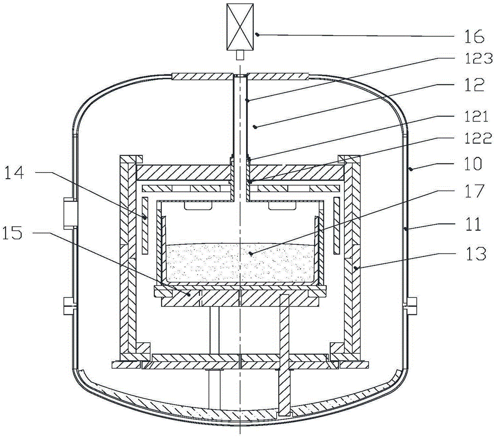
technical field [0001] The invention relates to a flow guide device, in particular to a flow guide device for guiding the flow direction of a carrier gas used in a polycrystalline ingot furnace, and belongs to the field of crystal growth equipment. Background technique [0002] The polycrystalline ingot casting furnace 10 is mainly composed of an infrared detector 16, a furnace body 11, a flow guiding device 12, a heat insulation cage 13, a heater 14, and a graphite platform 15, such as figure 1 shown. The flow guiding device 12 includes a graphite tube 123 , a coupling nut 121 and a flow guiding tube 122 . The upper end of the guide tube 122 is provided with an external thread that matches the internal thread of the fitting nut 121, and the upper end of the guide tube 122 passes through the through hole in the middle of the top insulation board of the heat insulation cage, and the matching hole above the top insulation board. The nut 121 is fixed, and the lower end of the...

Claims


Application Information

Patent Timeline
IPC IPC(8): C30B28/06C30B29/06
CPCC30B28/06C30B29/06
Inventor 陈鸽其他发明人请求不公开姓名
Owner 京山新瑞达通用机器有限公司
Learn More