

Prefabricated shear wall in cast-in-situ connection mode
A connection method and prefabricated shear force technology, applied in the direction of walls, building materials, building components, etc., can solve the problems of insufficient anchorage length of steel bars, difficulty in inspection, water seepage, etc., so as to improve the resistance to rainwater infiltration and reduce support Workload, the effect of increasing the contact area
- Summary
- Abstract
- Description
- Claims
- Application Information
AI Technical Summary
Problems solved by technology
Method used
Image

Examples
Embodiment Construction
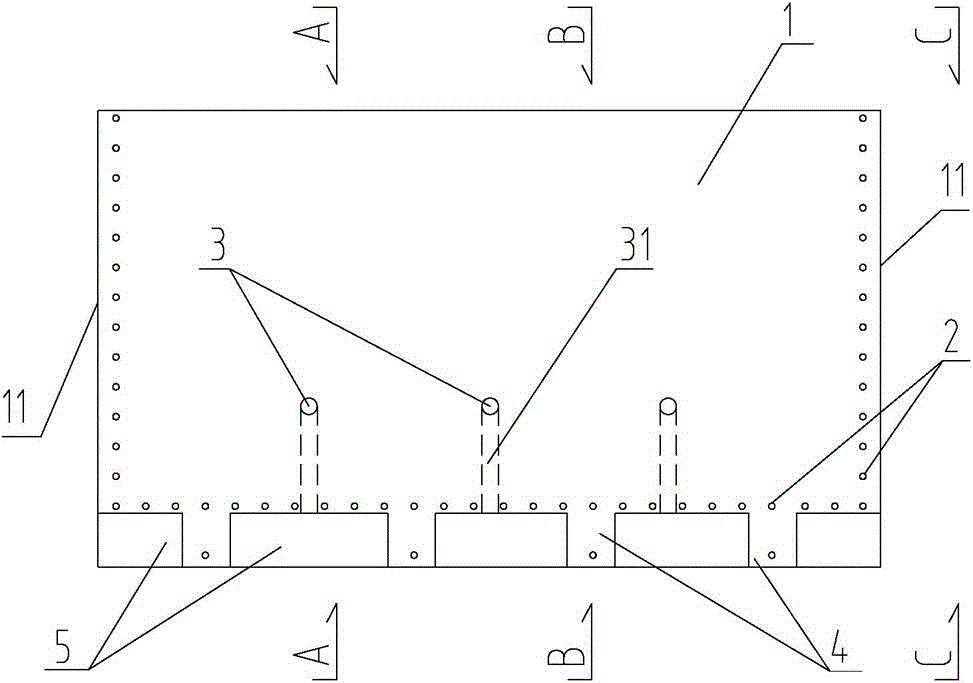
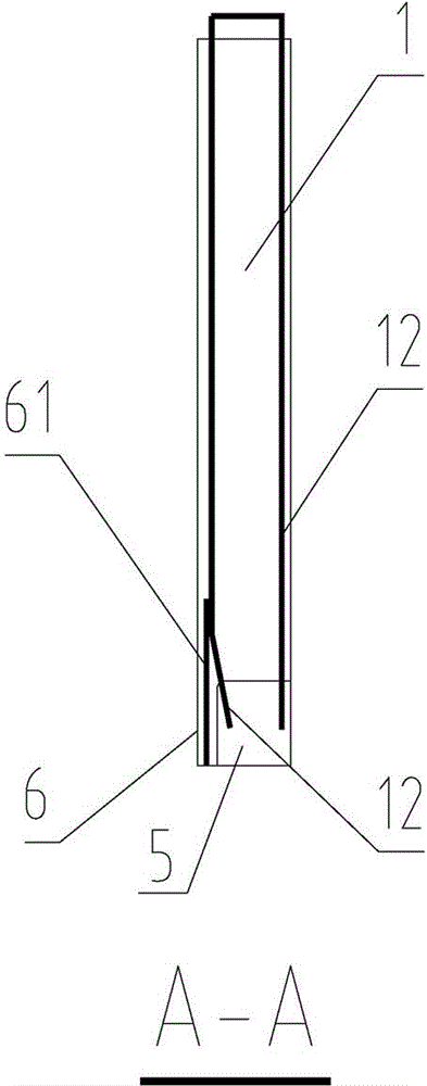
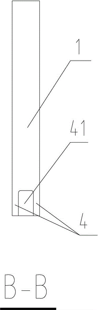
[0023] Please refer to the attached figure 1 to attach Figure 4 As shown, the present invention is a prefabricated shear wall adopting the cast-in-place connection method, which is composed of a wall body 1, a pier head 4, an upper concave section 5 at the bottom, and an outer side plate 6 at the bottom.
[0024] Wherein, the two sides of the wall body 1 are provided with side edges 11 respectively, and a groove 7 is arranged in the middle of each side edge 11 . The groove 7 runs through the wall up and down, which can effectively increase the contact area between the side 11 of the prefabricated wallboard and the cast-in-place part, and can effectively improve the resistance of the connection part between the prefabricated wallboard and the cast-in-place part to resist rainwater penetration during building use .
[0025] Vertical steel bars 12 are arranged inside the wall 1 . The vertical steel bars 12 of the wall do not need to be connected by pre-embedded grout anchor s...
PUM
| Property | Measurement | Unit |
|---|---|---|
| Height | aaaaa | aaaaa |
| Thickness | aaaaa | aaaaa |
| Diameter | aaaaa | aaaaa |
Abstract
Description
Claims
Application Information