Low-energy-consumption colloid grinder type emulsifying machine

A colloid mill and emulsifying machine technology, applied in the field of emulsifying machine, can solve the problems of wasting heating energy, service life discount, high motor power, etc., and achieve the effects of avoiding leakage, low power consumption, and improving overall sealing and service life.

Inactive Publication Date: 2016-06-01
太仓液压元件有限公司
View PDF7 Cites 1 Cited by
  • Summary
  • Abstract
  • Description
  • Claims
  • Application Information

AI Technical Summary

Problems solved by technology

However, it also has certain disadvantages while being continuously improved. For example, the existing emulsifying machine generally needs to go through 4-5 times of repeated grinding to reach the specified standard, which is a waste of time and heating energy, and the power of the equipped motor is large. , the overall production cost is very high, and in addition, medium leakage is prone to occur inside the device, so the service life is greatly reduced

Method used


Image

  • Low-energy-consumption colloid grinder type emulsifying machine

Examples


Embodiment 1

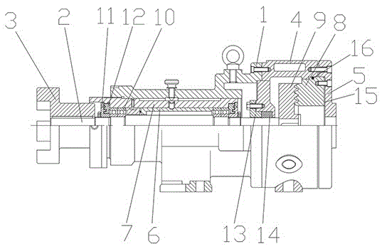
[0021] Such as figure 1 As shown, a low-energy colloid mill emulsifier in this embodiment includes a housing 1, a main shaft 2, a coupling 3, a stator housing 4, an end cover 5, a fixed sleeve 6, a sliding sleeve 7, a stator 8, Rotor 9, bearing 10, sealing cover 11, sealing ring 12, gland 13, packing 14, paper pad 15 and sealing ring 16; the two ends of the stator shell 4 are respectively connected with the shell 1 and the end cover 5, and the shell 1 There is a main shaft 2 inside, which has small overall volume, light weight and low power consumption; the shaft body of the main shaft 2 is sequentially connected with the coupling 3, the bearing 10 and the rotor 9, and the end of the rotor 9 and the stator 8 are equipped with an eight-layer cone. The rotor 9 and the stator 8 mesh with each other through the grinding teeth. Its unique internal tooth design, the eight-layer grinding teeth mesh with each other in a conical shape. When working, the turntable of the colloid mill ro...

Embodiment 2

[0024] Such as figure 1 As shown, a low-energy colloid mill emulsifier in this embodiment includes a housing 1, a main shaft 2, a coupling 3, a stator housing 4, an end cover 5, a fixed sleeve 6, a sliding sleeve 7, a stator 8, Rotor 9, bearing 10, sealing cover 11, sealing ring 12, gland 13, packing 14, paper pad 15 and sealing ring 16; the two ends of the stator shell 4 are respectively connected with the shell 1 and the end cover 5, and the shell 1 There is a main shaft 2 inside, which has small overall volume, light weight and low power consumption; the shaft body of the main shaft 2 is sequentially connected with the coupling 3, the bearing 10 and the rotor 9, and the end of the rotor 9 and the stator 8 are equipped with an eight-layer cone. The rotor 9 and the stator 8 mesh with each other through the grinding teeth. Its unique internal tooth design, the eight-layer grinding teeth mesh with each other in a conical shape. When working, the turntable of the colloid mill ro...


PUM


Abstract

The invention discloses a low-energy-consumption colloid grinder type emulsifying machine. The two ends of a stator shell of the emulsifying machine are connected with a shell body and an end cover correspondingly. The shell body is internally provided with a main shaft. A shaft body of the main shaft of the emulsifying machine is sequentially connected with a coupler, a bearing and a rotor in a matched mode. One end of the rotor and one end of a stator are each provided with eight layers of conical grinding teeth. The rotor and the stator are engaged with each other through the grinding teeth. A fixing sleeve, a sliding sleeve and the baring of the emulsifying machine are located in the shell body and connected with one another. A sealing cover and a sealing ring are arranged between the main shaft and the sliding sleeve and are connected with each other. A gland and fillers are sequentially arranged between the stator shell and the main shaft of the emulsifying machine. A paper washer is arranged between the stator and the end cover. A sealing washer is arranged at one end of the stator. The emulsifying machine has super high shearing and grinding functions, the production efficiency is high, energy consumption is low, the overall sealing performance of the emulsifying machine is remarkably improved, and the service life of the emulsifying machine is significantly prolonged.

Description

technical field [0001] The invention relates to the technical field of emulsifiers, in particular to a colloid mill emulsifier with low energy consumption. Background technique [0002] The emulsifying machine shears, disperses and impacts the materials through the high-speed rotation of the homogenizing head connected to the engine; generally, the materials processed by the emulsifying machine will become more delicate, which promotes the blending of oil and water, so the application field of the emulsifying machine Very extensive, such as adhesives, paint coatings, cosmetics, food, medicine, plastic resin, printing and dyeing, ink, asphalt and other industries have a wide range of applications. Its working process is mainly the precise cooperation of the rotor and the stator, and then through the high-speed and stable rotation of the rotor, thereby forming a high-frequency, strong circumferential tangential velocity, angular velocity and other comprehensive kinetic energy ...

Claims


Application Information

Patent Timeline
Patent Type & Authority Applications(China)
IPC IPC(8): B02C7/175B02C7/04B02C7/12B02C7/11B02C7/16
CPCB02C7/175B02C7/04B02C7/11B02C7/12B02C7/16
Inventor 施昌付
Owner 太仓液压元件有限公司
Why Eureka
Try Eureka