Intelligent pipeline pump

A technology of intelligent pipeline and pump shaft, applied in the direction of pump, pump control, pump device, etc., can solve the problems of large volume of frequency conversion control cabinet, aggravated environmental pollution, increased installation space, etc., to reduce manufacturing cost, reduce operating cost, reduce Small volume effect

Inactive Publication Date: 2016-06-01
池泉
View PDF5 Cites 8 Cited by
  • Summary
  • Abstract
  • Description
  • Claims
  • Application Information

AI Technical Summary

Problems solved by technology

For centrifugal pumps, the power consumption of the motor is approximately proportional to the cube of the rotational speed, and pipeline pumps operating at a fixed speed at power frequency will cause energy waste and aggravate environmental pollution. The current solution is to use ordinary pipeline pumps with frequency conversion Solutions for control cabinets
With the continuous improvement of energy saving and environmental protection requirements, there are more and more cases of using frequency conversion to control pipeline pumps and pump sets. However, due to the introduction of frequency converters, it is necessary to design independent frequency conversion control cabinets for arranging frequency converters and some auxiliary electronic components. , so that the system becomes more complex, and because the frequency conversion control cabinet is larger, the installation space of the entire frequency conversion water pump system is significantly increased; Under most working conditions, it does not work in an optimized state, and the efficiency is low under some working conditions

Method used


Image

  • Intelligent pipeline pump
  • Intelligent pipeline pump
  • Intelligent pipeline pump

Examples


Embodiment Construction

[0029] The following will clearly and completely describe the technical solutions in the embodiments of the present invention with reference to the drawings in the embodiments of the present invention.

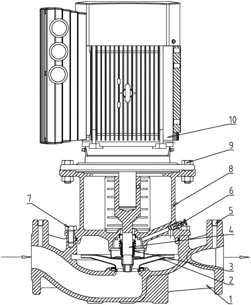
[0030] figure 1 It is a structural schematic diagram of the intelligent pipeline pump of the present invention, as figure 1 As shown, the intelligent pipeline pump of the present invention specifically includes: pump body 1, impeller 2, mechanical seal 3, pump shaft 4, sensor interface 5, exhaust hole 6, motor bracket 8, bolts connecting pump body 1 and motor bracket 8 7. The variable frequency motor 10, and the bolt 9 connecting the variable frequency motor 10 and the motor support 8.

[0031] refer to Figure 4 , the variable frequency motor 10 has a motor shaft 103, which drives the pump shaft 4 to rotate through the motor shaft 103, the pump shaft 4 transmits the power to the impeller 2, and the impeller 2 rotates to introduce the fluid through the inlet of the pump body...


PUM


Abstract

The invention discloses an intelligent pipeline pump. The intelligent pipeline pump comprises a pump body, a pump shaft, an impeller, a variable frequency motor and a motor support, wherein the pump shaft is contained in the pump body, and the section of an inner hole of the motor end of the pump shaft is in a non-circular shape; the impeller is assembled on the pump shaft in a key joint mode; the variable frequency motor is integrally composed of a variable frequency controller and a motor body, and the motor body is used for driving the pump shaft to rotate; the motor support is used for connecting the pump body and the variable frequency motor. The variable frequency motor integrally composed of the variable frequency controller and the motor body is adopted, the size of the motor can be reduced, product manufacturing cost is lowered, and installation space is reduced; the efficiency of the variable frequency motor under partial load working conditions is considered while rated point optimization design is considered, the efficiency under partial working conditions of a pipeline pump system is improved, and thus the operation cost of the variable frequency pipeline pump system is reduced. By means of the non-circular section, the inner hole of the motor end of the pump shaft is assembled in transition fit with a motor shaft of the variable frequency motor, so that machining cost is lowered, higher torque can be transmitted, and a powerful communication function is achieved.

Description

technical field [0001] The invention relates to the fields of industrial liquid transportation and urban water supply and drainage, in particular to an intelligent pipeline pump driven by a frequency conversion motor integrated with a frequency converter motor. Background technique [0002] Pipeline pumps are used in the transportation of industrial liquids and urban water supply and drainage, pressurized water supply for high-rise buildings, garden sprinkler irrigation, fire pressurization, heating and other cold and warm water cycle pressurization and equipment matching, air conditioning unit circulation, cooling water delivery, etc. [0003] At present, most pipeline pumps work at power frequency (50Hz) during use. In practical applications (such as domestic water supply in buildings), the pump system does not need to work at the rated flow rate and rated head in most of the working hours, but needs to work under partial load conditions (that is, the flow rate required ...

Claims


Application Information

Patent Timeline
Patent Type & Authority Applications(China)
IPC IPC(8): F04D13/06F04D15/00
CPCF04D13/06F04D15/0066
Inventor 陈拥军钱北磊
Owner 池泉
Why Eureka
Try Eureka