
Shoot range multimode fusion placement measurement system

A measurement system and multi-mode technology, which is applied in the field of multi-mode fusion drop point measurement system in the end area of ​​the shooting range, can solve the problems that optical measurement methods are easily affected by climate conditions, and are easily affected by climate conditions, achieving low price, saving time, and cost reduction effect

Active Publication Date: 2016-06-01
BEIJING INST OF AEROSPACE CONTROL DEVICES
View PDF11 Cites 9 Cited by
  • Summary
  • Abstract
  • Description
  • Claims
  • Application Information

AI Technical Summary

Problems solved by technology

This method is a photoelectric measurement method, which is mainly used to measure the three-dimensional coordinates of the explosion point of the proximity fuze of the artillery shell, and is easily affected by the weather conditions as an optical measurement method
[0009] The authorized announcement number is CN202649229U, a utility model patent named "a laser reflection type large surface speed measurement light curtain target", which discloses a method of using a laser reflection type large surface speed measurement light curtain target. The method mainly Measure the flight speed of high-speed small target objects, not for the purpose of measuring the impact point, and it is easily affected by weather conditions

Method used


Image

  • Shoot range multimode fusion placement measurement system
  • Shoot range multimode fusion placement measurement system
  • Shoot range multimode fusion placement measurement system

Examples


Embodiment Construction

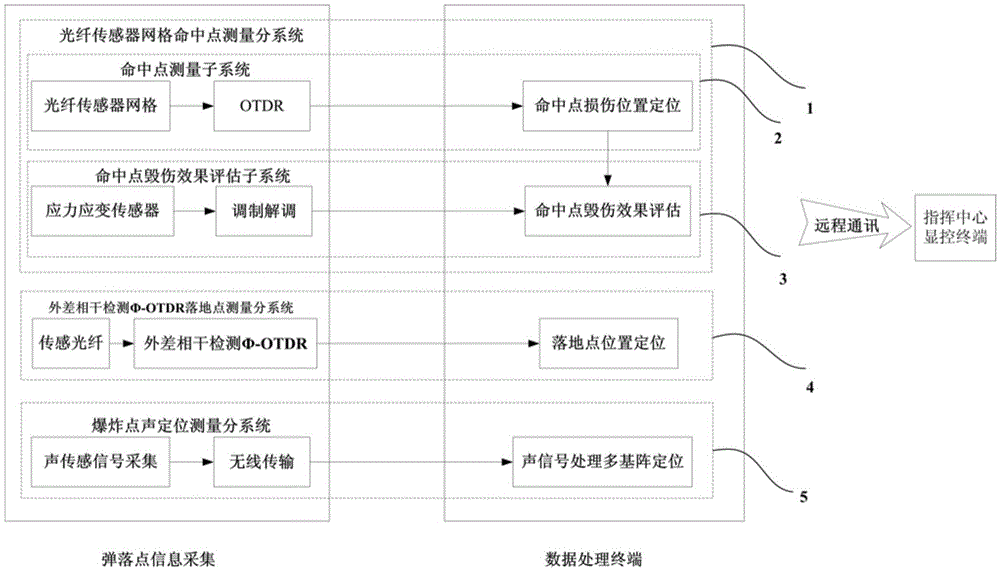
[0040] Such as figure 1 As shown, the present invention includes: optical fiber sensor grid hit point measurement subsystem 1, heterodyne coherent detection Φ-OTDR fall point measurement subsystem 4 and explosion point acoustic positioning measurement subsystem 5; fiber optic sensor grid hit point measurement subsystem 1 includes hit point measurement subsystem 2 and hit point damage effect evaluation subsystem 3.

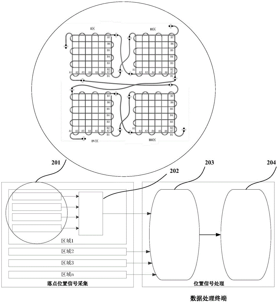
[0041] figure 2 It shows that the hit point measurement subsystem 2 includes an optical fiber sensor grid 201, a multi-channel OTDR 202, an OTDR information reading module 203, and an impact location module 204. information for statistical analysis.

[0042] The two ends of the optical fiber sensor grid 201 are respectively connected to the multi-channel OTDR202, arranged in a staggered way of latitude and longitude, in a "well" shape layout, each longitude and latitude optical fiber is coded with a fixed code, any two adjacent longitude or latitude The sensing...


PUM

PropertyMeasurementUnit
Bending diameteraaaaaaaaaa

Abstract

The invention provides a shoot range multimode fusion placement measurement system comprising an optical fiber sensor grid hit point measurement subsystem, a heterodyne coherent detection phi-OTDR placement measurement subsystem and a burst point acoustic positioning measurement subsystem. The system is used for high-precision positioning of missile burst points and placement of a shoot range and assessment of the hit point damage effect. Omnibearing measurement of target hit, air burst and ground placement can be realized by a multiregional optical fiber sensor grid, multi-array acoustic sensors and surface / subsurface sensing optical fibers. All-weather and omnibearing measurement and assessment of actual combats under various working conditions can be met, a real-time shoot indication function of the shoot range can be realized, continuous multi-target placement measurement can be realized through fusion of multiple measurement modes, and high-precision placement positioning and assessment of the hit point damage effect can be realized so that the shoot range multimode fusion placement measurement system has advantages of high reliability, low construction cost and high precision.

Description

technical field [0001] The invention relates to a multi-mode fusion impact point measurement system in the end area of ​​the shooting range. The system is based on OTDR technology, acoustic positioning technology and optical fiber sensing technology, and adopts a multi-mode fusion measurement method, which is applied to the impact point measurement technology in the end area of ​​the shooting range. field. Background technique [0002] With the improvement of the accuracy of the weapon system, higher requirements are put forward for the reliability and accuracy of the shooting range drop point measurement. In order to complete the measurement task of the shooting range, data reliability and all-weather measurement are two important considerations. [0003] At present, optical methods such as infrared automatic tracking, infrared miss-target measurement, target infrared radiation characteristic measurement and thermal image live recording have been widely used in missile aer...

Claims


Application Information

Patent Timeline
IPC IPC(8): G01S17/02G01S17/06G01S5/20G01S5/22G01S5/00
CPCG01S5/0036G01S5/20G01S5/22G01S17/06G01S17/86
Inventor 胡常青孙巧英杨勇李清洲李成志马林朱炜炜袁唐杰曾笑尘范慧佳
Owner BEIJING INST OF AEROSPACE CONTROL DEVICES
Learn More