
Automatic gain control system and control method for AGC (Automatic Gain Control) loop

An automatic gain control and loop technology, applied in gain control, amplification control, electrical components, etc., can solve the problems of careless detailing of the process, inability to accurately measure the instantaneous attenuation of voltage control, and high delay of fluctuating signals

Active Publication Date: 2016-06-01
BC P INC CHINA NAT PETROLEUM CORP +1
View PDF7 Cites 12 Cited by
  • Summary
  • Abstract
  • Description
  • Claims
  • Application Information

AI Technical Summary

Problems solved by technology

[0007] The existing automatic gain control methods and their limitations: the existing automatic gain control is divided into two categories, analog AGC and digital AGC, which can only deal with stable envelope signals, and there is a high delay for fluctuating signal processing. Disadvantage of big error
Its disadvantage is: due to the characteristics of the digital circuit itself, the response time of the AGC loop is slow, and the detector needs to convert the detected analog signal into a digital signal, and then send it to the attenuator after comparison in the digital signal processing part. The response time is related to the processing speed of the digital circuit, and the output response time cannot be artificially guaranteed
However, because the control gain at a certain moment is determined by the analog voltage, the instant attenuation of the voltage control cannot be accurately measured, the stability of the signal amplitude cannot be guaranteed, the detection error is large, and the principle and circuit of the analog AGC are vague and general, making it difficult for users to use
[0008] There are only a small number of finished AGC chips on the market, such as the high-frequency AGC chip and the intermediate-frequency AGC chip provided by HITTIE, but the process is accidentally detailed, and the operating frequency range of the high-frequency AGC chip is 700MHz-3GHz, which cannot meet the requirements Other frequency bands, especially the application of higher frequency band circuits
For the design of other frequency bands, designers often have to study complex principles and build circuits with a variety of discrete components to meet the needs, which is time-consuming and laborious, and is incompatible with the social rhythm of high-speed wealth creation.

Method used


Image

  • Automatic gain control system and control method for AGC (Automatic Gain Control) loop
  • Automatic gain control system and control method for AGC (Automatic Gain Control) loop
  • Automatic gain control system and control method for AGC (Automatic Gain Control) loop

Examples


Embodiment Construction

[0082] The present invention will be described in further detail below in combination with specific embodiments.

[0083] In order to make the object, technical solution and advantages of the present invention clearer, the present invention will be further described in detail below.

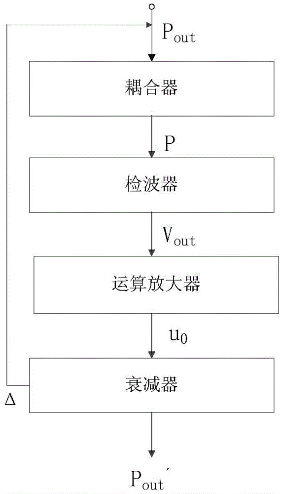
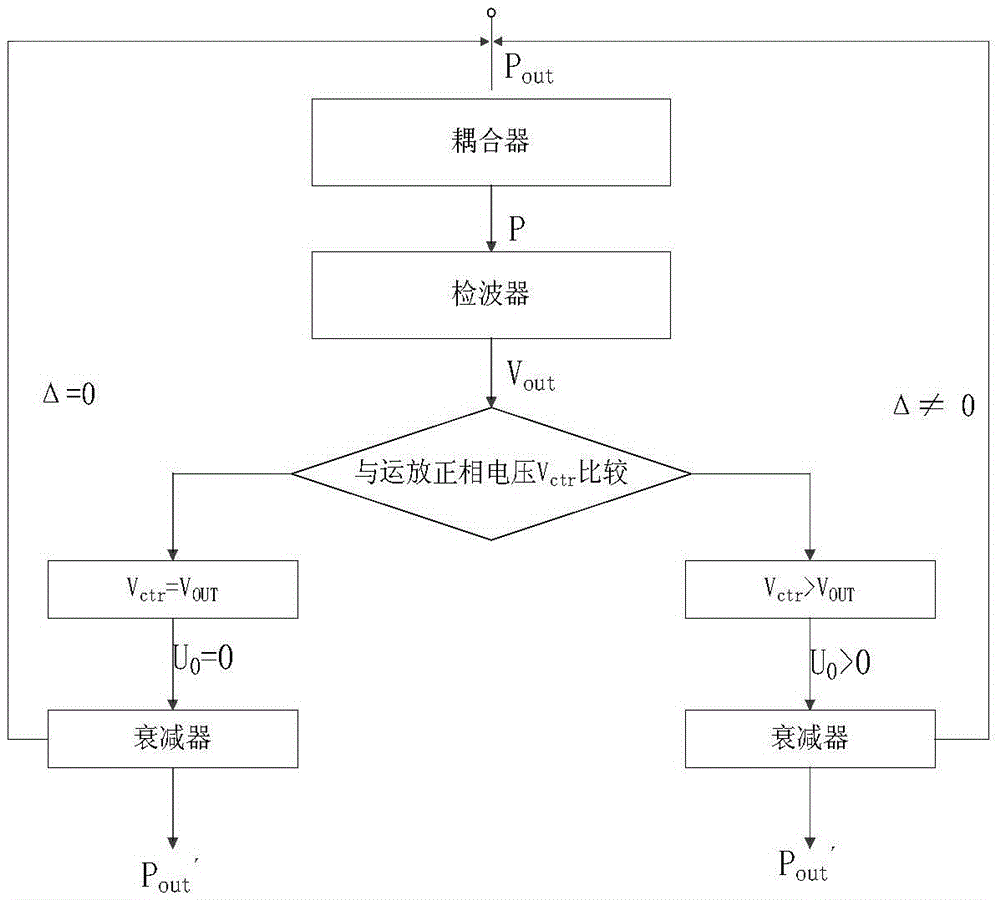
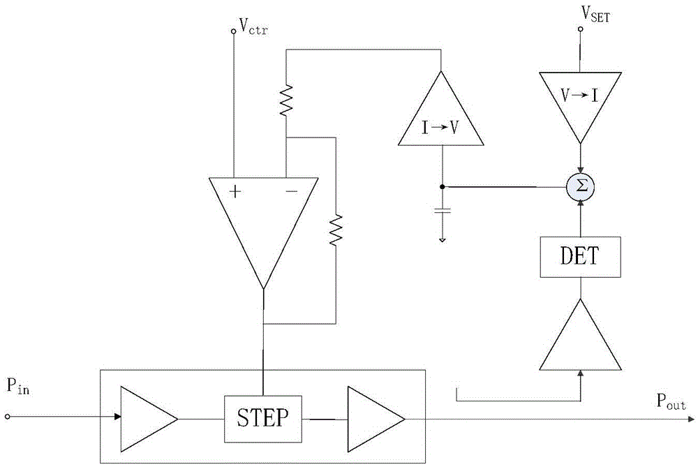
[0084] The basic idea of ​​the present invention is: the coupler sends the output power to the detector, the detector converts the power signal into a voltage and outputs it to the post-stage operational amplifier, and the output voltage of the operational amplifier is used as the attenuator control signal to control the attenuation of the input power, thus To achieve the dynamic balance of the loop. Since the control voltage of the detector in the loop has a quantitative relationship with the input power, the user can directly obtain the control voltage of the detector according to the required output power, thereby further obtaining the parameter range of other devices. Select the appropriate ...


PUM


Abstract

The invention discloses an automatic gain control system and control method for an AGC (Automatic Gain Control) loop. Cascading cooperation of an attenuator, a coupler, a detector and an amplifier is adopted to form the AGC loop, wherein an output power signal of a microwave source enters the attenuator, an output power of the attenuator is coupled by the coupler to enter the detector, the detector detects an input signal, the signal is controlled to be output to the operational amplifier by controlling a voltage, and the operational amplifier receives an output voltage of the detector and according to a working mode of the detector, feeds the output voltage into a control voltage port of the attenuator. The control voltage of the detector in the loop has a quantitative relationship with an input power, and a user can directly obtain the control voltage of the detector according to the size of a required output power, thereby obtaining the parameter ranges of other devices. According to the parameter ranges, the suitable devices are selected to set up the circuit; the automatic gain control system and control method are simple, rapid, convenient, time-saving and labor-saving.

Description

technical field [0001] The invention belongs to the technical field of high-frequency signal measurement, relates to oil well logging high-frequency detection, and particularly relates to an automatic gain control system and a control method of an AGC loop. Background technique [0002] In recent years, with the continuous development of the world's oil industry, the number of drilling wells has increased dramatically, and the number of oil and gas wells in many old oil fields (such as Shengli Oilfield and Yumen Oilfield) has become saturated. The recovery of oil and gas is becoming more and more difficult and unrealistic, so improving the recovery of old oil and gas wells will be an important direction, so it is necessary to re-log these old oil and gas wells, that is, to further describe the target oil and gas layers in detail, so as to Determine remaining oil and gas saturation. Since water flooding is commonly used in most oil and gas fields, in order to determine the r...

Claims


Application Information

Patent Timeline
Patent Type & Authority Applications(China)
IPC IPC(8): H03G3/30
CPCH03G3/30
Inventor 贺秋利徐方友侯学理张宝仪苟仲荣侯建强
Owner BC P INC CHINA NAT PETROLEUM CORP
Learn More