
Power-on reset circuit

A technology of electric reset and circuit, applied in the direction of electrical components, electronic switches, pulse technology, etc., can solve problems such as influence, achieve the effect of reducing discreteness and improving performance

Inactive Publication Date: 2016-06-01
SHANGHAI HUAHONG GRACE SEMICON MFG CORP
View PDF4 Cites 8 Cited by
  • Summary
  • Abstract
  • Description
  • Claims
  • Application Information

AI Technical Summary

Problems solved by technology

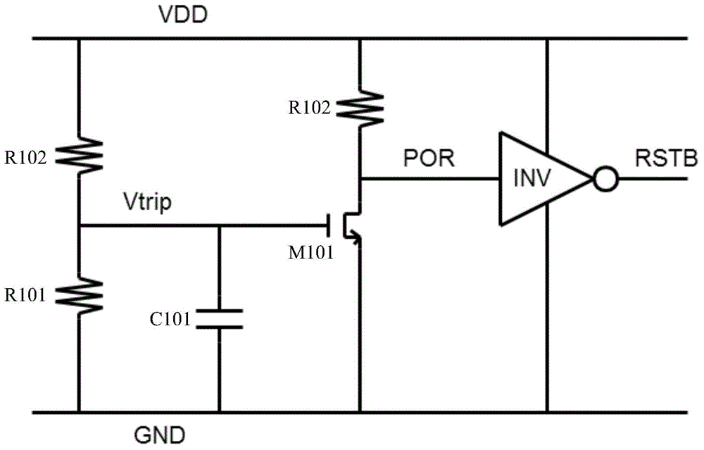
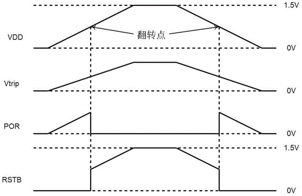
[0013] Equation (4) is the V obtained by substituting Equation (1) and Equation (2) into Equation (3) DD with V THN101 It can be seen that the flipping voltage Vtrip of the existing power-on reset circuit will be directly affected by the threshold voltage of the NMOS transistor M101
However, in a semiconductor integrated circuit, the threshold voltage of the NMOS transistor M101 will not remain constant. The same NMOS transistor M101 will change with changes in voltage and temperature, and the threshold voltages of the NMOS transistors formed at different positions on the same wafer will also be different from each other. There will be differences between them, and there will also be differences between the threshold voltages of NMOS transistors formed on different wafers using the same process, due to the V DD between and V THN101 is proportional to, and the proportionality factor is greater than 1, which will make V DD will be subject to V THN101 effect, and finally make the discreteness of the flipping voltage

Method used


Image

  • Power-on reset circuit
  • Power-on reset circuit
  • Power-on reset circuit

Examples


Embodiment Construction

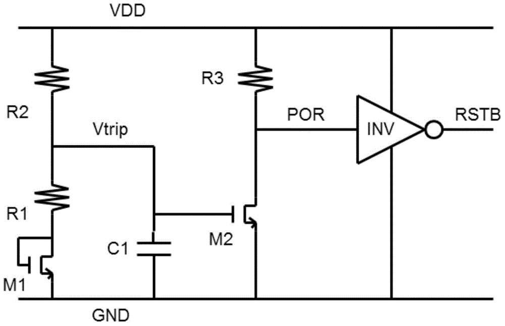
[0027] Such as image 3 Shown is the circuit diagram of the power-on reset of the embodiment of the present invention; the power-on reset circuit of the embodiment of the present invention includes:

[0028] A first voltage divider circuit connected between the power supply voltage VDD and ground GND, the first voltage divider circuit is formed by a plurality of resistors connected in series with a first NMOS transistor M1, the output terminal of the first voltage divider circuit outputs the The voltage division of the power supply voltage VDD is used as the flipping voltage Vtrip, and the gate and drain of the first NMOS transistor M1 are short-circuited and connected in series between the output terminal of the first voltage dividing circuit and the ground GND.

[0029] Preferably, the resistor string of the first voltage divider circuit includes a first resistor R1 and a second resistor R2, and the second resistor R2 is connected between the power supply voltage VDD and the...


PUM


Abstract

The invention discloses a power-on reset circuit. The circuit comprises a first voltage division circuit connected between a power supply voltage and the ground. A plurality of resistors and one first NMOS tube are serially connected to form the first voltage division circuit. A grid electrode and a drain electrode of the first NMOS tube are serially connected between an output end of the first voltage division circuit and the ground. A source electrode of a second NMOS tube is grounded, a grid electrode is connected with an overturn voltage output by the first voltage division circuit, and a drain electrode is connected with the power supply voltage through a third resistor. The drain electrode of the second NMOS tube outputs a power-on reset signal. The power-on reset signal is reversed by an inverter, and then a reset signal is output. According to the invention, the first NMOS tube is capable of compensating the threshold voltage of the second NMOS tube controlled by the overturn voltage, so that the influences of the threshold voltage of the second NMOS tube on the power-on process when the threshold voltage of the second NMOS tube changes along with PVT are reduced, and the discreteness of the overturn voltage is lowered.

Description

technical field [0001] The invention relates to a semiconductor integrated circuit, in particular to a power-on reset circuit. Background technique [0002] The digital circuit (digital) part in the integrated circuit (IC) chip of the mixed-signal very large-scale integrated circuit (VLSI) will cause the chip to not work normally due to the unsteady state of the power supply during the power-on process. The power-on reset circuit (PowerOnReset, POR) that provides a reset signal, and the trip voltage (Tripvoltage) of the POR circuit is seriously affected by the process PVT. In the field of semiconductor integrated circuit manufacturing, PVT is the process, voltage and temperature conditions that the device meets In general, the process, voltage and temperature all have a certain error range; therefore, because the devices of the circuit are affected by PVT, the performance parameters of the devices will not be exactly the same, such as the threshold voltage of the MOS transis...

Claims


Application Information

Patent Timeline
Patent Type & Authority Applications(China)
IPC IPC(8): H03K17/22
Inventor 张健忠
Owner SHANGHAI HUAHONG GRACE SEMICON MFG CORP
Learn More