Light source system and projection equipment

A light source system and light source technology, applied in the field of optics, can solve the problems of low utilization efficiency of red light, and achieve the effect of avoiding light loss and improving light utilization efficiency

Active Publication Date: 2016-06-08
APPOTRONICS CORP LTD
View PDF6 Cites 26 Cited by
  • Summary
  • Abstract
  • Description
  • Claims
  • Application Information

AI Technical Summary

Problems solved by technology

[0011] In view of this, the present invention provides a light source system and projection equipment to solve the prob

Method used


Image

  • Light source system and projection equipment
  • Light source system and projection equipment
  • Light source system and projection equipment

Examples


Embodiment 1

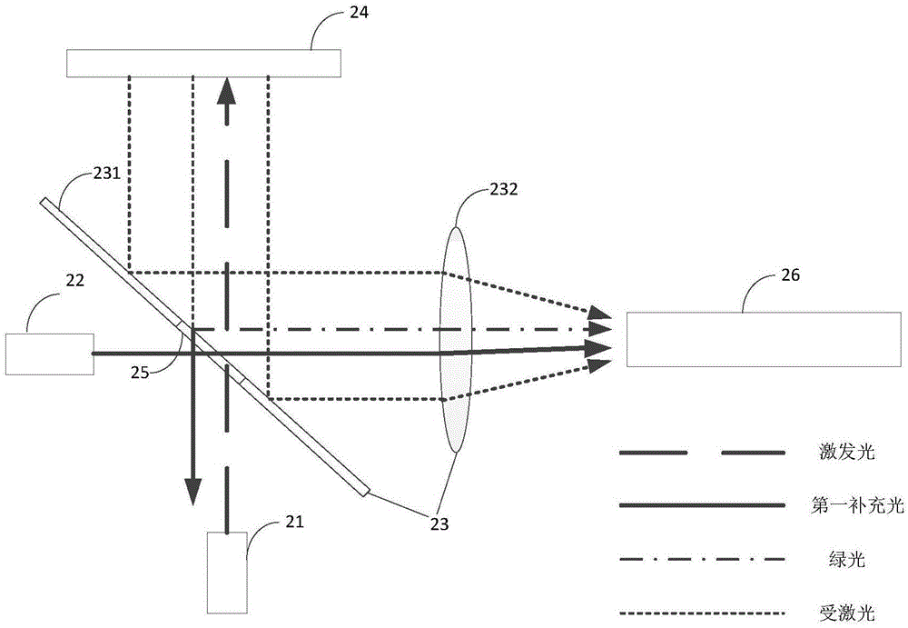
[0047] This embodiment provides a light source system, such as figure 2 As shown, the light source system includes two light sources, respectively an excitation light source 21 and a first supplementary light source 22 , and also includes a first light guiding component 23 , a wavelength converting device 24 , a second light guiding component 25 and a light homogenizing device 26 . In this embodiment, the first light guiding component 23 and the second light guiding component 25 realize light splitting and combination by using wavelengths. The first light guiding component 23 includes a filter 231 having a central film and edge films, and the second light guiding component 25 is the central film of the filter 231 . in:

[0048] The excitation light source 21 emits excitation light. The excitation light source 21 is a semiconductor diode or a semiconductor diode array. The semiconductor diode may be a laser diode (LD) or a light emitting diode (LED). The excitation light i...

Embodiment 2

[0067] This embodiment provides another light source system, please refer to Figure 4 , the light source system and figure 2 The difference of the light source system shown is that the second light guiding member 25 realizes light splitting and combining by means of etendue. Specifically, it is replaced by a reflective sheet 431 with a through hole figure 2 A filter 231 with a central diaphragm and edge diaphragms. In this embodiment, the first light guiding component 43 includes a reflective sheet 431 having a through hole, and the second light guiding component 25 is the through hole on the reflective sheet 431 .

[0068] Wherein the size of the through hole is smaller than the size of the reflection sheet 431 . The size of the through hole can be determined according to one or more combinations of the light loss when the first supplementary light passes through the through hole, the light loss when the excitation light passes through the through hole, and the light lo...

Embodiment 3

[0071] This embodiment provides another light source system, such as Figure 5 As shown, the light source system and figure 2 The difference of the light source system shown is that the second light guiding component realizes light splitting and combining by using polarization state. Specifically: the optical filter 531 in the light source system includes a polarizer and an edge film, wherein the edge film is the same as the edge film in Embodiment 1, and the difference is that figure 2 The central diaphragm of the middle optical filter 231 is replaced by a polarizer.

[0072] In this embodiment, the first light guiding component 53 is a filter 531 having a polarizer and an edge film, and the second light guiding component 25 is a polarizing plate in the filter 531 . The polarizer reflects light having a first polarization state and transmits light having a second polarization state. Wherein the first polarization state is the P state and the second polarization state is ...


PUM


Abstract

The invention provides a light source system and projection equipment. The light source system comprises at least two light sources, a wavelength conversion device, a first light guide component and a second light guide component; the two light sources comprise an exciting light source and a first supplement light source, the exciting light source is used for emitting exciting light, the first light guide component is used for guiding the exciting light to the wavelength conversion device and guiding the emergent excited light emitted of the wavelength conversion device to a dodging device, the wavelength conversion device is used for converting the exciting light into the excited light and emits the excited light to the first light guide component, the first supplement light source emits first supplement light, and optical extend of the first supplement light is smaller than that of the excited light; the second light guide component is used for guiding the first supplement light to the dodging device, and the second light guide component is smaller than that first light guide component. The light use ratio of the first supplement light can be increased greatly.

Description

[0001] This application is a divisional application based on the patent application with the application number 201410284185.3, the invention name is light source system and projection equipment, and the application date is 2014-06-23. technical field [0002] The present invention relates to the field of optical technology, more specifically, to a light source system and projection equipment. Background technique [0003] At present, solid-state light sources have been widely used in general lighting, special lighting and projection display due to their long life and environmental protection. Among them, the white light solid-state light source has great development potential in the field of lighting. [0004] The prior art provides a white light source that uses laser to excite phosphor powder to achieve ultra-high brightness. The white light source uses a blue-violet laser with a wavelength of 440nm-455nm to excite yellow phosphor powder of YAG:Ce material to generate hig...

Claims


Application Information

Patent Timeline
IPC IPC(8): G03B21/20
CPCG03B21/2013G03B21/204
Inventor 胡飞侯海雄
Owner APPOTRONICS CORP LTD
Why Eureka
Try Eureka