Power control device with dynamic driving ability regulation function

A power control device and drive capability technology, applied in the direction of adjusting electric variables, output power conversion devices, control/regulation systems, etc., can solve problems such as inability to reduce electromagnetic interference, large conduction current, and increase EMI adverse effects at the same time

Inactive Publication Date: 2016-06-08
产晶积体电路股份有限公司
View PDF5 Cites 1 Cited by
  • Summary
  • Abstract
  • Description
  • Claims
  • Application Information

AI Technical Summary

Problems solved by technology

However, the disadvantage of the prior art is that only different first gate resistors RG1 and second gate resistors RG2 can be configured to change the turn-on time and turn-off time of the switching transistor M1 by the drive signal VD1, although the switching loss can be moderately reduced, but Cannot reduce electromagnetic interference at the same time
That is, when the switch transistor needs to be turned on, the conduction current in the original off state is 0 or close to 0, so if the driving voltage rises rapidly at this time, it is not helpful to reduce the switching loss, but instead Will increase the adverse effects of EMI
On the other hand, when the switching transistor is partially turned on or fully turned on, the conduction current is quite large. At this time, if the driving voltage rises or falls slowly, it will cause a lot of power loss during the entire switching process.

Method used


Image

  • Power control device with dynamic driving ability regulation function
  • Power control device with dynamic driving ability regulation function
  • Power control device with dynamic driving ability regulation function

Examples


Embodiment Construction

[0065] The following describes the embodiments of the present invention in more detail with the accompanying drawings and reference numerals, so that those skilled in the art can implement them after studying this specification.

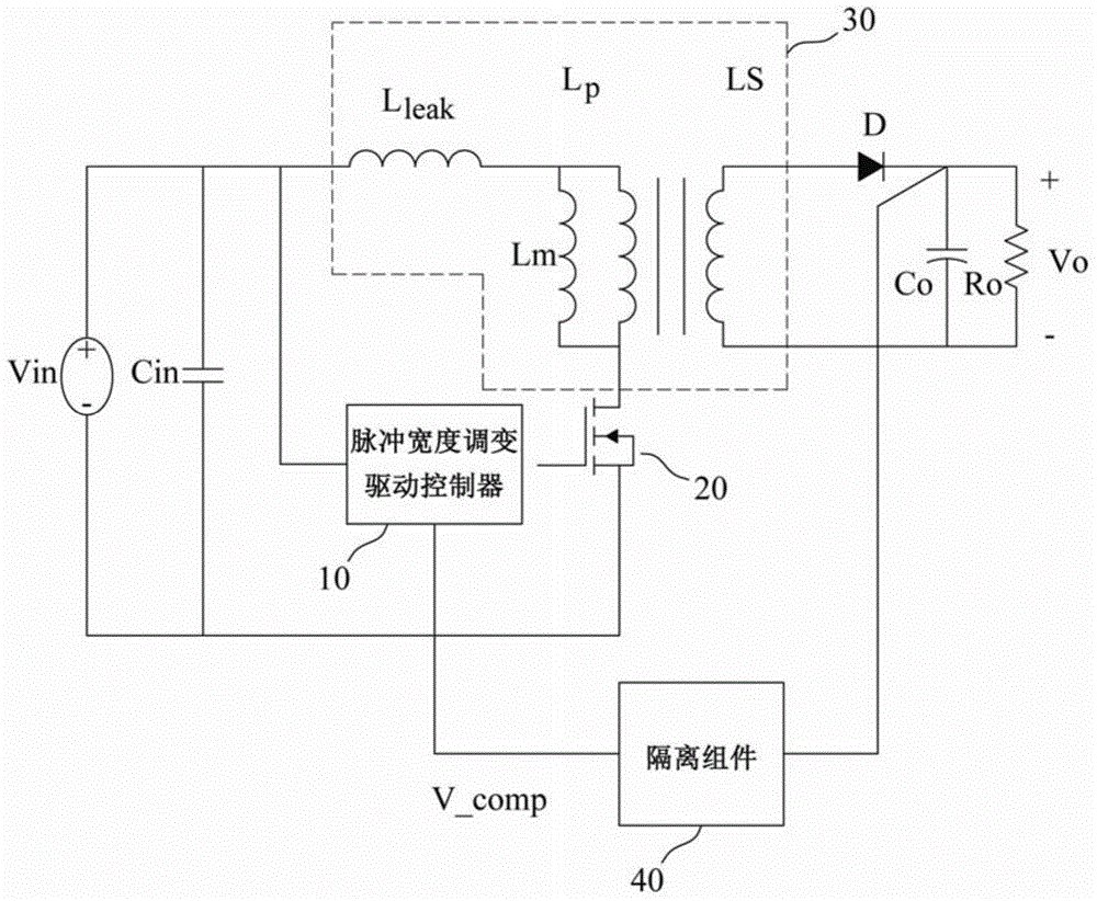
[0066] reference figure 2 , A schematic diagram of a power control device for dynamic driving capability adjustment according to an embodiment of the present invention. Such as figure 2 As shown, the power control device for dynamic drive capability adjustment of the present invention includes a pulse width modulation (PWM) drive controller 10, a switching transistor 20, a transformer 30, an isolation component 40, an output diode D, and an output capacitor Co to convert the input The input power of the voltage Vin is converted into an output power with an output voltage Vo and supplied to the external load Ro. The transformer 30, the pulse width modulation drive controller 10, the switching transistor 20 and the input power with the input voltage Vin ...


PUM


Abstract

The invention relates to a power control device with a dynamic driving ability regulation function, comprising a transformer, a pulse width modulation driving controller, a switching transistor, an isolation component, an output diode and an output capacitor, wherein the pulse width modulation driving controller is connected with the switching transistor, the switching transistor is connected with the transformer, a primary inductor of the transformer and the switching transistor are connected with an input power supply, and a secondary inductor of the transformer is connected with the output diode and further connected with the output capacitor and a load. The isolation component converts an output power supply into a feedback signal and sends the feedback signal to the pulse width modulation driving controller, and the pulse width modulation driving controller adjusts the feedback signal and dynamically controls a pulse width modulation driving signal to achieve optimal switching-on current of the switching transistor. The electromagnetic interference margin is increased, the switching loss is reduced, and the overall electrical quality and power conversion efficiency are improved.

Description

Technical field [0001] The present invention relates to a power control device for dynamic driving capability adjustment, in particular, the use of adjustment processing, in view of the state of the switching transistor, while considering electromagnetic interference (EMI) and switching loss, to dynamically adjust the pulse width modulation driving signal, thereby improving Electrical quality and overall power conversion efficiency. Background technique [0002] Power conversion technology is very important to the increasingly booming electronics industry, because different electronic products require different voltages or currents to operate. For example, integrated circuits (ICs) require 5V or 3V, electric motors require 12V direct current, and lamps in liquid crystal displays require higher voltage power supplies, such as 1150V. Therefore, different power converters are needed to meet the requirements. [0003] In the prior art, switching (switching) power conversion technolog...

Claims


Application Information

Patent Timeline
Patent Type & Authority Applications(China)
IPC IPC(8): H02M3/335
Inventor 林树嘉林敬渊林志峰谢文岳
Owner 产晶积体电路股份有限公司
Why Eureka
Try Eureka