Processing method and device for polarization-maintaining optical fiber pigtail in non-melting point optical fiber gyroscope

A fiber optic gyroscope and polarization-maintaining optical fiber technology, applied in the field of optical fiber pigtail processing, can solve the problems of difficult control of axis positioning accuracy, low efficiency of axis positioning, poor consistency, etc.

Active Publication Date: 2013-06-19
BEIJING AEROSPACE TIMES OPTICAL ELECTRONICS TECH
View PDF0 Cites 6 Cited by
  • Summary
  • Abstract
  • Description
  • Claims
  • Application Information

AI Technical Summary

Problems solved by technology

The problems with these methods are that the human factor accounts for a large proportion, the precision of axis fixing is not easy to control, and is closely related to human experience, and the efficiency of axis fixing is also low, and the curing

Method used


Image

  • Processing method and device for polarization-maintaining optical fiber pigtail in non-melting point optical fiber gyroscope
  • Processing method and device for polarization-maintaining optical fiber pigtail in non-melting point optical fiber gyroscope
  • Processing method and device for polarization-maintaining optical fiber pigtail in non-melting point optical fiber gyroscope

Examples


Embodiment Construction

[0072] The present invention will be described in further detail below in conjunction with the accompanying drawings and specific embodiments.

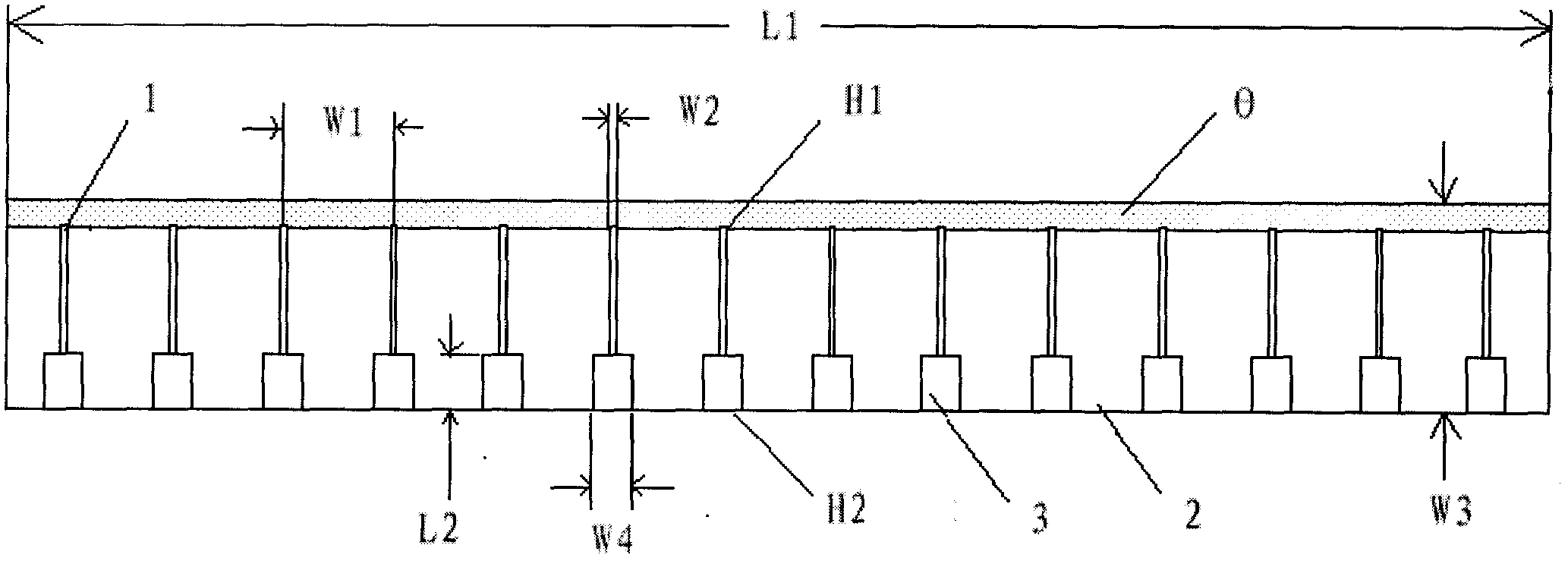
[0073] Such as figure 1 Shown is a schematic diagram of the structure of the fiber fixing block array of the present invention. It can be seen from the figure that the fiber fixing block array 2 is provided with a plurality of parallel grooves 1 and a plurality of boring grooves 3 connected with the grooves 1, wherein the end faces of the fiber fixing block array 2 are inclined The angle of the angle is 15°, and the preparation method of the optical fiber fixing block array 2 is as follows:

[0074] (1) Select LiNbO with a diameter of 3 inches 3 The wafer is scribed in the Y direction to form groove 1, the scribed groove index W1=2.5 mm, the groove width W2=135 microns, the groove depth H1=70 microns, after scribing, the wafer is rotated 90°, and then divided according to W3= 4.5 mm for cutting, when the wafer is completely diced, t...


PUM

PropertyMeasurementUnit
Depthaaaaaaaaaa
Widthaaaaaaaaaa
Depthaaaaaaaaaa

Abstract

The invention relates to a method and device for processing polarization-maintaining optical fiber pigtails in a non-melting point optical fiber gyroscope. The processing method includes preparing an array of optical fiber fixed blocks, a fixed axis of polarization-maintaining optical fiber pigtails, a polarization-maintaining optical fiber ring tail fiber together with an array of fixed blocks and an array of accompanying blocks. Grinding and polishing together and dividing the optical fiber fixed block array after polishing. The invention also provides an improved axis-fixing device for polarization-maintaining optical fiber pigtails. The end face processing is carried out on the same array fixed block together, instead of the traditional method of fixing the axis of a single optical fiber fixed block, which greatly improves the processing efficiency, makes the product consistent, and the process is simple. The card reduces the difficulty of card installation, and the end-face structure of the polarization-maintaining fiber can be clearly observed by setting an external light source and collecting images by a computer, which improves the axis positioning accuracy.

Description

technical field [0001] The invention relates to a processing method for an optical fiber pigtail, in particular to a processing method and device for a polarization-maintaining optical fiber ring pigtail directly coupled with a waveguide chip. Background technique [0002] The fiber optic gyroscope is a new type of all-solid-state optical gyroscope based on the Sagnac effect. With the characteristics of high precision, light and small size, long life, short start-up time, large dynamic range, and good environmental adaptability, it has become the mainstream gyro instrument in the field of inertial guidance and measurement in the 21st century. However, the manufacturing technology and process of the passive optical path of high-precision and high-quality fiber optic gyroscopes has always been one of the main technical bottlenecks hindering the performance improvement of fiber optic gyroscopes. The key process of the fiber optic gyroscope passive optical path packaging is how...

Claims


Application Information

Patent Timeline
IPC IPC(8): G01C19/72
Inventor 李瑞龙刘福民汪飞琴黄韬郑国康
Owner BEIJING AEROSPACE TIMES OPTICAL ELECTRONICS TECH
Why Eureka
Try Eureka