
Machine tool sliding plate structure

A technology of machine tools and skateboards, which is applied in the direction of metal processing machinery parts, large fixed members, metal processing equipment, etc., can solve the problems of ram design and extension length increase, uneven temperature distribution of skateboards, and difficulty in ensuring processing accuracy, etc. To achieve the effect of reducing thermal deformation error, reducing height and reducing volume

Active Publication Date: 2016-06-15
BEIJING UNIV OF TECH
View PDF10 Cites 3 Cited by
  • Summary
  • Abstract
  • Description
  • Claims
  • Application Information

AI Technical Summary

Problems solved by technology

[0002] At present, the processing parts of complex and large molds continue to increase, which leads to the gradual increase in the design and extension length of the ram, and it is difficult to ensure the processing accuracy
[0003] Geometric error and thermal deformation are the main error sources that affect the machining accuracy of machine tools. The former can be reduced by advanced manufacturing technology. However, when the machine tool is working, due to the long extension of the ram, the vibration is more obvious. Therefore, it is necessary to set a counterweight system to reduce its bending deformation, and the traditional skateboard is generally made very long, which is not conducive to the installation of the counterweight system; when the machine tool is running, the heat generated by the motor, the friction heat of the transmission system and the change of the external environment temperature will cause the temperature distribution of the skateboard Unevenness, which in turn produces thermal deformation, which affects the processing accuracy. The traditional skateboard is equipped with a servo motor, and its thermal deformation is serious.

Method used


Image

  • Machine tool sliding plate structure
  • Machine tool sliding plate structure
  • Machine tool sliding plate structure

Examples


Embodiment Construction

[0016] The specific implementation manners of the present invention will be further described in detail below in conjunction with the accompanying drawings and embodiments. The following examples are used to illustrate the present invention, but are not intended to limit the scope of the present invention.

[0017] In the description of the present invention, it should be noted that the orientation or positional relationship indicated by the terms "up", "down", "X direction" and "Y direction" are based on the orientation or positional relationship shown in the accompanying drawings, only It is for the convenience of describing the present invention and simplifying the description, rather than indicating or implying that the device or element referred to has a specific orientation, is constructed and operates in a specific orientation, and thus should not be construed as limiting the present invention.

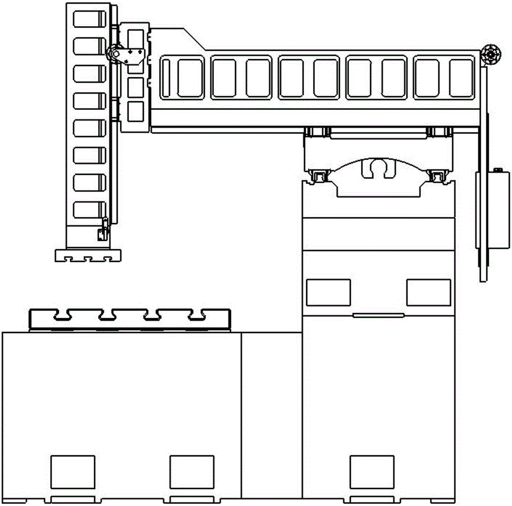
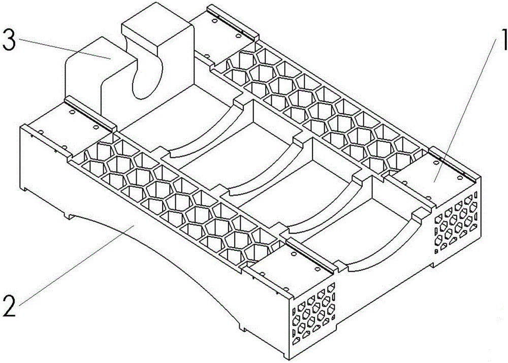
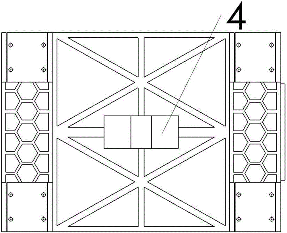
[0018] This kind of machine tool slide plate structure includes a slider m...


PUM


Abstract

The invention discloses a machine tool sliding plate structure. Mounting platforms of a guide track sliding block are arranged on both the upper surface and the lower surface of the machine tool sliding plate structure, oil holes are formed in side surfaces of the mounting platforms, and the oil holes are beneficial for flowing of oil, so that a gap caused by surface roughness between a sliding block and a sliding plate can be filled, heat transfer can be enhanced, part of heat in the heat conduction process can be carried away, then thermal deformation of the sliding plates can be reduced, and meanwhile a lubricating function can be achieved for guide track pairs; the lower surface is saddle-shaped and is internally provided with a cross-shaped rib plate; an X-direction ball screw pair screw nut base is integrally connected with the sliding plate and is arranged at a central part of the lower surface; honeycomb rib plates are arranged on the upper surface and the lower surface; a Y-direction ball screw pair screw nut base is arranged at one end of the upper surface; under the condition that the Y-direction stroke is ensured, the length of a ram can be reduced. Compared with a conventional sliding plate, the volume and the mass of the improved sliding plate can be both reduced, a weight system can be conveniently arranged on the ram on the sliding plate, the strength and the rigidity of the structure can be improved, thermal deformation can be reduced, and the machining precision of a machine tool can be improved.

Description

technical field [0001] The invention relates to an improved invention of a slide plate structure of a honeycomb ribbed machine tool, in particular to a slide plate structure applied to a precision machining machine tool equipped with a counterweight system. Background technique [0002] At present, the number of processing parts of complex and large molds is increasing, which leads to the gradual increase of the design and extension length of the ram, and it is difficult to guarantee the processing accuracy. [0003] Geometric error and thermal deformation are the main error sources that affect the machining accuracy of machine tools. The former can be reduced by advanced manufacturing technology. However, when the machine tool is working, due to the long extension of the ram, the vibration is more obvious. Therefore, it is necessary to set a counterweight system to reduce its bending deformation, and the traditional skateboard is generally made very long, which is not condu...

Claims


Application Information

Patent Timeline
IPC IPC(8): B23Q1/62B23Q1/01
CPCB23Q1/017B23Q1/621
Inventor 李富平李迎刘志峰赵林忠
Owner BEIJING UNIV OF TECH
Learn More