Linear frequency-modulated signal microwave photon frequency multiplication method and device

A technology of linear frequency modulation signal and microwave photon, which is applied in the direction of radio wave measurement system, instrument, etc., can solve the problems of unable to filter and suppress spurious sidebands, increase frequency multiplication coefficient, and electric phase shifter can not be accurately shifted.

Inactive Publication Date: 2016-06-15
AIR FORCE UNIV PLA
View PDF0 Cites 30 Cited by
  • Summary
  • Abstract
  • Description
  • Claims
  • Application Information

AI Technical Summary

Problems solved by technology

[0005] However, the above scheme has certain limitations
In the schemes 1) and 2), the frequency multiplication factor only reaches 4. To generate an ultra-wideband chirp signal, the input signal needs to have a wide bandwidth, so the dependence on the input circuit is high, and the advantages of microwave photon frequency multiplication are not fully utilized.
On the other hand, in view of the characteristics of the wide spectrum of the chirp signal, the non-line

Method used


Image

  • Linear frequency-modulated signal microwave photon frequency multiplication method and device
  • Linear frequency-modulated signal microwave photon frequency multiplication method and device
  • Linear frequency-modulated signal microwave photon frequency multiplication method and device

Examples


Example Embodiment

[0070] Example

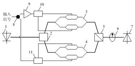
[0071] In order to verify the frequency multiplication performance of the chirp signal of the present invention, the Optisystem simulation platform is used to perform the frequency multiplication processing of the chirp signal. In the simulation, the input signal is a baseband chirp signal with a bandwidth of 100MHz and a time width of 1024ns, and the laser output optical signal frequency 193.1THz, power 13dBm, an optical amplifier is added after the polarization coupler for power amplification, the gain is 10dB, and the detector responsivity is 0.9A / W.
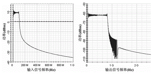
[0072] figure 2 Is the modulation factor m 1 = 4, m 2 =1, the DC bias phase θ=0, and the analyzer angle β=27°, the frequency spectrum of the input chirp signal and the output detection signal. The output signal bandwidth reaches 800MHz, and the frequency multiplication factor of this microwave photon frequency multiplication system is 8.
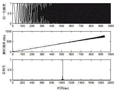
[0073] image 3 Output the time-domain waveform diagram, instantaneous freq...


PUM


Abstract

The invention provides a linear frequency-modulated signal microwave photon frequency multiplication method and device. Under a large signal modulation mode, two parallel Mach-Zehnder modulators which are connected in parallel are utilized to generate high-order nonlinear optical sidebands; direct current bias phase positions and modulation coefficients of the two modulators are adjusted, so that in the optical sidebands output by the two modulators, required optical sidebands are the same in phase and stray optical sidebands are opposite in phase; polarization of the optical sidebands output by the two modulators are orthogonally coupled, and a polarization detection angle of an analyzer is adjusted, so that the stray optical sidebands is equal are power and completely counteracted, thereby obtaining the required optical sidebands; and linear frequency-modulated signals of eightfold frequency and twelvefold frequency are generated through frequency beating by detector, in the scheme, suppression of stray sidebands does not need optical filtering processing or any electrical phase shift processing, tuning performance of a system is good, and the linear frequency-modulated signal microwave photon frequency multiplication method and device are suitable for frequency multiplication processing of arbitrary waveform signals such as single-frequency microwave millimeter wave signals, linear frequency-modulated signals and nonlinear chirp signals, and have very broad application prospects.

Description

technical field [0001] The invention belongs to the technical field of microwave photon signal processing, and in particular relates to a microwave photon frequency doubling method and device for a linear frequency modulation signal. Background technique [0002] Chirp signal is one of the most commonly used radar signal forms. It has a large time-width bandwidth product, which can improve the measurement accuracy and resolution of radar distance and speed at the same time. On the other hand, chirp signal has excellent pulse compression Features, can improve the range and measurement accuracy of the radar at the same time. With the continuous development of technology, the requirements for the accuracy and resolution of radar equipment are getting higher and higher. Especially in the field of military combat, it is urgent to improve the ability of radar to accurately detect, locate, and image. Therefore, the chirp signal needs to have a wider bandwidth. . The generation of...

Claims


Application Information

Patent Timeline
IPC IPC(8): G01S7/481
CPCG01S7/481
Inventor 李轩赵尚弘李勇军朱子行
Owner AIR FORCE UNIV PLA
Why Eureka
Try Eureka