
Charging control method, charging equipment, and charging system

A charging control method and technology for charging equipment, applied in charging stations for charging mobile devices, charging/discharging secondary batteries, battery circuit devices, etc., capable of solving problems such as poor heat dissipation, unstable communication, and inability to realize intensive adjustment of charging equipment And other issues

Active Publication Date: 2016-06-22
MEIZU TECH CO LTD
View PDF4 Cites 27 Cited by
  • Summary
  • Abstract
  • Description
  • Claims
  • Application Information

AI Technical Summary

Problems solved by technology

The low-level noise tolerance and high-level noise tolerance of the interface are insufficient. When the IRdrop of the cable is greater than a certain level, the communication between the portable electronic terminal and the charging device cannot be carried out stably.
[0013] The second prior art realizes the one-way communication with the charging device by alternately pumping power with a certain regular high current and small current at the electronic terminal. The first disadvantage is that only the portable electronic terminal can communicate with the charging device in one direction, and the charging device cannot For portable electronic terminals to send signals, the second disadvantage is that the transmission instructions are limited, and the intensive adjustment of the output voltage of the charging device cannot be realized. The second disadvantage is that the charging current inevitably decreases during the transmission process, prolonging the charging time
[0014] The third prior art achieves communication between the portable electronic terminal and the charging device by alternately changing the levels of the first signal line and the second signal line through the portable electronic terminal. It is impossible to send signals to portable electronic terminals. The second disadvantage is that the transmitted instructions are limited, and the intensive adjustment of the output voltage of the charging device cannot be realized.
[0023] It can be seen that no matter whether high-voltage fast charging or low-voltage fast charging is used, when the charging current is large or the number of insertions increases to a certain extent, the communication level between the single-chip microcomputer placed on the charging device end and the single-chip microcomputer placed in the electronic terminal has exceeded Its normal tolerance range, the communication will not be stable
[0024] 2. The problem of high cable power loss and low transmission efficiency during low-voltage fast charging
[0029] 3. Low-voltage fast charging requires high cable impedance, and the charging cable has poor versatility.
[0032] 4. Low-voltage fast charging is sensitive to changes in the impedance of the charging connector, and the service life of the charging cable is short
With the increase of the number of plugging and unplugging, the pins at the contact position of the connector are worn, oxidized, dirty, and deformed. When the impedance of the connector circuit increases to 40mR, P=I 2 *R power loss is 0.81W. Due to the small metal area of ​​the MICRO connector and poor heat dissipation, the power loss of 0.81W has exceeded the preset safety value. This cable will not continue to be used for low-voltage fast charging.
[0034] 5. Existing high-voltage charging technology has a big problem with mobile phone heating
Taking the ambient temperature of 25°C as an example, the temperature of the mobile phone is 25+27.5=52.5°C. The direct consequence of the temperature of the mobile phone reaching 52.5°C is to affect the comfort of the user's hand-holding. The serious consequence is that the battery expands or explodes after being charged with high temperature and high current. The solution adopted by the high-voltage fast charging technology is to use a temperature sensor to detect the temperature of the mobile phone, and reduce the charging power when it reaches the preset value, which can control the temperature rise within a safe range, but at the same time prolong the charging time and slow down the fast charging speed
[0036] In addition, the fast charging method in the prior art cannot well adjust the charging current, voltage, etc. according to the state of the battery, so that there is a certain risk in the charging process.

Method used


Image

  • Charging control method, charging equipment, and charging system
  • Charging control method, charging equipment, and charging system
  • Charging control method, charging equipment, and charging system

Examples


Embodiment Construction

[0098] The following will clearly and completely describe the technical solutions in the embodiments of the present invention with reference to the accompanying drawings in the embodiments of the present invention. Obviously, the described embodiments are only some, not all, embodiments of the present invention. Based on the embodiments of the present invention, all other embodiments obtained by persons of ordinary skill in the art without making creative efforts belong to the protection scope of the present invention.

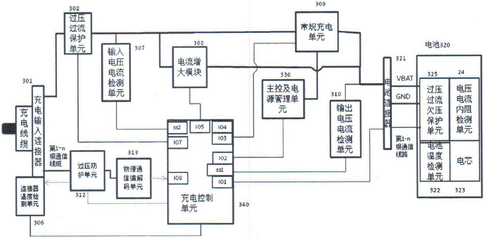
[0099] Such as image 3 Shown is an embodiment of the electronic terminal in the charging system of the present invention, which includes a charging input connector 301, an overvoltage and overcurrent protection unit 302, an input voltage and current detection unit 307, a current increasing module 308, and a charging control unit 340. Physical communication codec unit 313, signal line overvoltage protection unit 312, connector temperature detection unit 306, c...


PUM


Abstract

The invention relates to a charging control method, charging equipment, and a charging system. The method comprises the following steps: obtaining a voltage value of a rechargeable battery of an electronic terminal, and judging whether the voltage value is within a first preset voltage range or not: transmitting a first control signal if the voltage value is within the first preset voltage range; setting a first output voltage according to the control signal, and starting a first charging module for charging the battery; outputting the control signal through obtaining the voltage value of the rechargeable battery, and controlling the first charging module to start for charging the battery, thereby achieving the charging control according to the actual voltage condition of the rechargeable battery, and guaranteeing the high efficiency and safety of a charging process. Furthermore, the method can monitor the current output voltage and current output current of charging equipment and the input current and voltage of the electronic terminal through the communication between the charging equipment and the electronic terminal, controls the quick setting, and further improves the speed and safety of quick charging.

Description

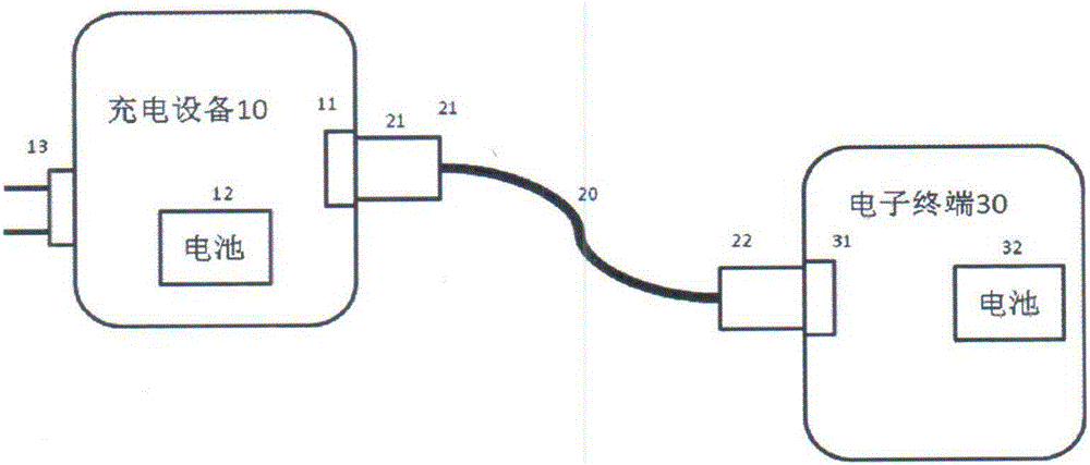
technical field [0001] The invention relates to the technical field of fast charging, in particular to a charging control method, charging equipment and a charging system. Background technique [0002] With the improvement of the configuration of portable electronic terminals, especially smart electronic terminals, the power consumption is also increasing. In recent years, the battery capacity improvement technology has encountered bottlenecks under the same volume, which can no longer meet the battery life requirements of smart portable electronic terminals. It is getting longer and longer, which has seriously affected the user experience. [0003] Such as figure 1 Shown is a block diagram of an example charging environment of an electronic terminal in the prior art. The environment includes a charging device 10 capable of providing a charging current via a charging output connector 11 . The charging device 10 may have a power plug 13 to obtain power from a conventional...

Claims


Application Information

Patent Timeline
IPC IPC(8): H02J7/00H01M10/44
CPCH01M10/44H02J7/0027H02J2207/10Y02E60/10
Inventor 王富明
Owner MEIZU TECH CO LTD
Learn More