Copper alloy wire, copper alloy stranded wire, coated electric wire, wire harness and manufacturing method of copper alloy wire

A technology of copper alloy wire and manufacturing method, which is applied in the direction of cable/conductor manufacturing, parts of conductive core, metal/alloy conductor, etc., and can solve problems such as characteristics that cannot have strength

Inactive Publication Date: 2016-06-22
AUTONETWORKS TECH LTD +2
View PDF11 Cites 20 Cited by
  • Summary
  • Abstract
  • Description
  • Claims
  • Application Information

AI Technical Summary

Problems solved by technology

However, even when the conductor is simply reduced in diameter, there are cases where requirements such as strength characteristics cannot be met.

Method used


Image

  • Copper alloy wire, copper alloy stranded wire, coated electric wire, wire harness and manufacturing method of copper alloy wire
  • Copper alloy wire, copper alloy stranded wire, coated electric wire, wire harness and manufacturing method of copper alloy wire
  • Copper alloy wire, copper alloy stranded wire, coated electric wire, wire harness and manufacturing method of copper alloy wire

Examples


Embodiment 1

[0058] Examples related to the above-mentioned copper alloy wire and its manufacturing method will be described together with comparative examples. In this example, copper alloy wires having the chemical composition shown in Table 1 were produced and evaluated. Samples 1-1 to 1-17 contain Fe: 0.4 mass % to 2.5 mass %, Ti: 0.01 mass % to 1.0 mass %, Mg, Sn, Ag, Ni, In, Zn, Cr, Al, One or two or more elements selected from P: a total of 0.01% by mass to 2.0% by mass, and a copper alloy wire having a chemical composition of Cu and unavoidable impurities in the remainder. On the other hand, sample C101 as a comparative example is a copper alloy containing only Fe and a small amount of Ti as alloying elements, and sample C102 is a copper alloy containing only Mg as an alloying element.

[0059] In the production of copper alloy wire, first, electrolytic copper with a purity of 99.99% or more and a master alloy containing various additive elements are put into a high-purity carbona...

Embodiment 2

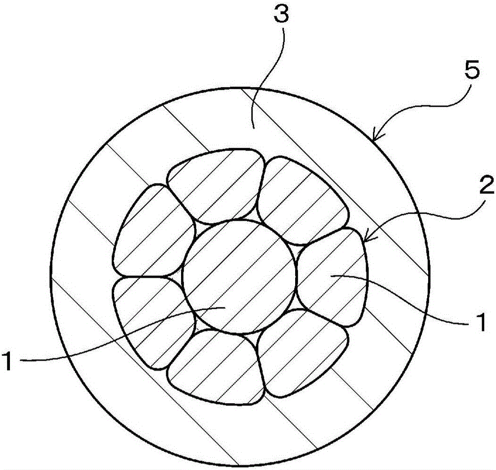
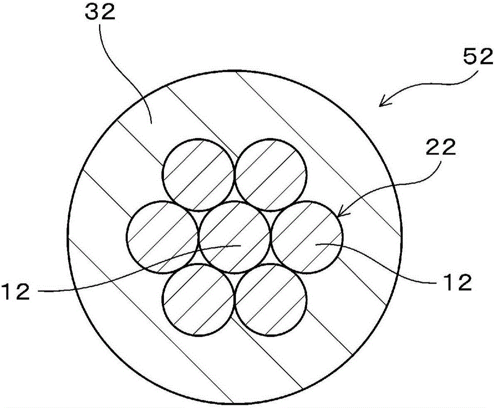
[0066] In this example, after producing copper alloy wires having the chemical composition shown in Table 2, a twisted wire obtained by twisting seven copper alloy wires was produced and evaluated. Samples 2-1 to 2-15 contain Fe: 0.4 mass % to 2.5 mass %, Ti: 0.01 mass % to 1.0 mass %, Mg, Sn, Ag, Ni, In, Zn, Cr, Al, One or two or more elements selected from P: a total of 0.01% by mass or more and 2.0% by mass or less, and a stranded wire having a chemical composition of Cu and unavoidable impurities in the remainder. On the other hand, sample C201 as a comparative example is a copper alloy containing only Fe and a small amount of Ti as alloying elements, and sample C202 is a copper alloy containing only Mg as an alloying element.

[0067] In the production of copper alloy wire, first, electrolytic copper with a purity of 99.99% or more and a master alloy containing various additive elements are put into a high-purity carbonaceous crucible and vacuum-dissolved in a continuous ...


PUM

PropertyMeasurementUnit
tensile strengthaaaaaaaaaa
areaaaaaaaaaaa
elongationaaaaaaaaaa

Abstract

The invention provides a copper alloy wire, a copper alloy stranded wire, a coated electric wire, a wire harness and a manufacturing method of the copper alloy wire. This copper alloy wire used as the conductor in a wire for use in vehicles contains 0.4-2.5 mass% Fe, 0.01-1.0 mass% Ti, and a total of 0.01-2.0 mass% of one or more species selected from Mg, Sn, Ag, Ni, In, Zn, Cr, Al and P, the remainder being Cu and unavoidable impurities. The O content is preferably 20ppm or less. The tensile strength is preferably 450MPa or greater. The element wire stretchability is preferably 5% or greater. The conductivity is preferably 62% IACS or greater.

Description

technical field [0001] The present invention relates to copper alloy wires, copper alloy stranded wires, covered electric wires, and methods for producing copper alloy wires, and in particular, to copper alloy wires, copper alloy stranded wires, and covered electric wires preferably used in electric wires for automobiles And the manufacturing method of copper alloy wire. Background technique [0002] As part of the weight reduction requirements of automobiles, it is required to reduce the weight of electric wires for automobiles. Weight reduction of electric wires for automobiles can be achieved by reducing the diameter of the conductors. However, even when the conductor is simply reduced in diameter, there are cases where requirements such as strength characteristics cannot be met. [0003] For example, for branching of electric wires, conductors of a plurality of electric wires may be joined to each other by ultrasonic welding, and the ultrasonic welded portion is requir...

Claims


Application Information

Patent Timeline
Patent Type & Authority Applications(China)
IPC IPC(8): C22C9/00C22C9/01C22C9/02C22C9/04C22C9/06C22F1/08H01B1/02H01B5/02H01B5/08H01B7/00H01B13/00C22F1/00
CPCC22C9/00C22F1/08H01B1/026B22D21/005C22C9/01C22C9/02C22C9/04C22C9/06B21C1/02H01B7/0009H01B7/0045H01B13/0006H01B13/0016
Inventor 小林启之中村匡宏井上明子大塚保之
Owner AUTONETWORKS TECH LTD
Why Eureka
Try Eureka