
MEMS silicon microphone and preparation method for the same

A silicon microphone and silicon-based technology, which is applied in the field of MEMS silicon microphone and its preparation, can solve the problems of failing to meet the sensitivity requirements of the vibrating film, reducing the sensitivity of the vibrating film, and complicating the preparation process, so as to improve sensitivity and yield, avoid Suction and possibility, good consistency effect

Active Publication Date: 2016-06-29
HUAJING SENSING TECH (WUXI) CO LTD
View PDF3 Cites 33 Cited by
  • Summary
  • Abstract
  • Description
  • Claims
  • Application Information

AI Technical Summary

Problems solved by technology

In the prior art process, the preparation of the vibrating film will cause it to have different degrees of residual stress, so the sensitivity of the vibrating film will be greatly reduced
[0006]The traditional technical solution mainly uses polysilicon or metal and silicon nitride stack as the main material of the vibration film, and improves the sensitivity of the vibration film through the following aspects First, if the material of the vibrating film is polysilicon, additional annealing treatment is required for the prepared vibrating film. Although this technical solution can reduce the residual stress, it is far from meeting the sensitivity requirements of the vibrating film; second, If the material of the vibrating film is silicon nitride or polysilicon, the residual stress can be reduced by adjusting the ratio of the reaction gases during preparation, but this method has little effect on reducing the residual stress, and the repeatability is not good. It is also relatively complicated; thirdly, by modifying the mechanical structure of the vibrating film, the method of changing the structure of the vibrating film will complicate the preparation process, increase the cost and reduce the yield

Method used

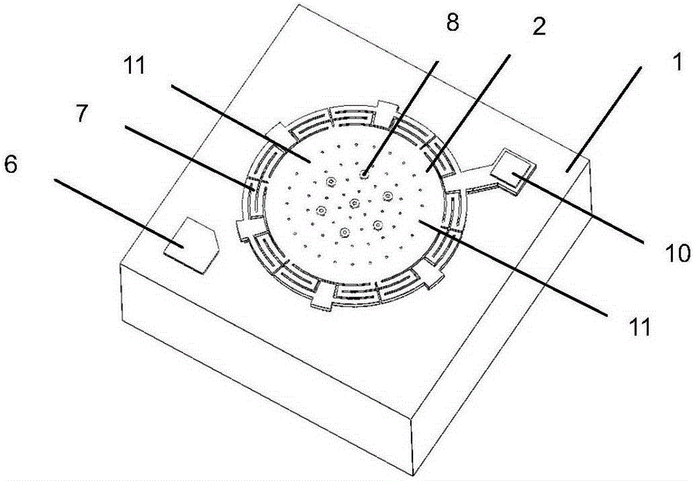
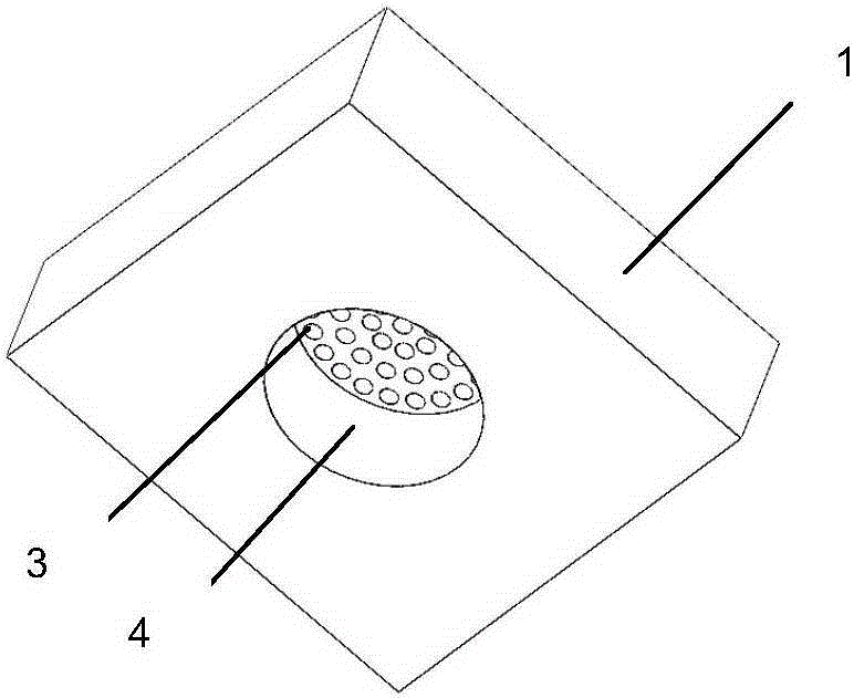
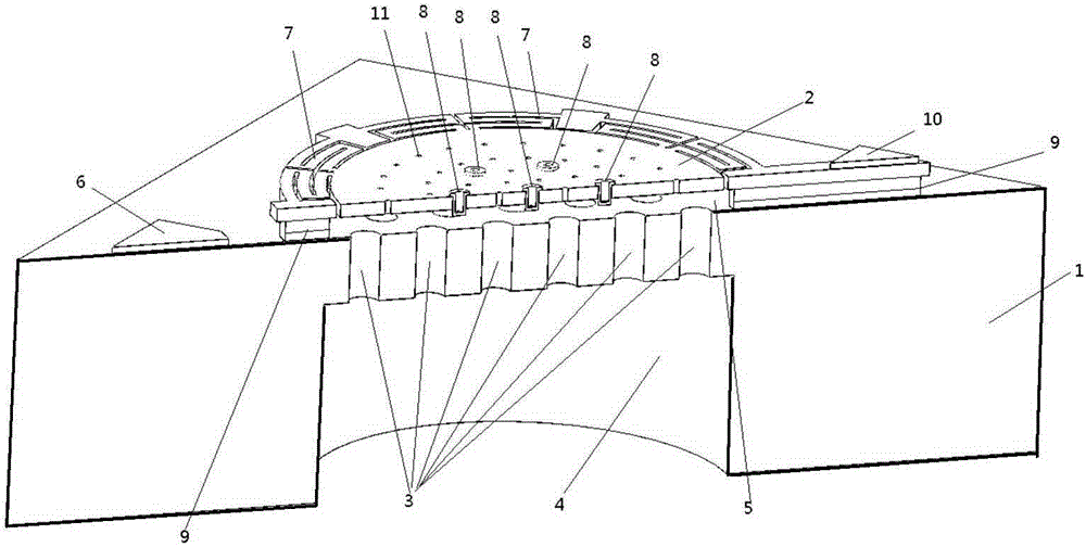

Image

  • MEMS silicon microphone and preparation method for the same
  • MEMS silicon microphone and preparation method for the same
  • MEMS silicon microphone and preparation method for the same

Examples


Embodiment Construction

[0046] Combine below Attached picture The present invention will be further described with specific examples, but the protection scope of the examples of the present invention is not limited to the following examples.

[0047] In view of the deficiencies and defects in the prior art, the present invention provides a MEMS silicon microphone and its preparation method. The technical solution of the invention can be realized on the basis of simplifying the manufacturing process of the MEMS silicon microphone, and can also meet the requirements of sensitivity, reliability and output. aspects of demand.

[0048] In order to thoroughly understand the present invention, detailed steps and detailed structures will be provided in the following description, so as to illustrate the technical solution of the present invention. Preferred embodiments of the present invention are described in detail below, however, the present invention may have other embodiments besides these detailed des...


PUM

PropertyMeasurementUnit
aperture sizeaaaaaaaaaa

Abstract

The invention relates to the silicon microphone technology field and particularly relates to an MEMS silicon microphone and a preparation method for the same. The method comprises steps of arranging a monocrystal silicon diaphragm above a silicon substrate of a porous back polar plate, performing separation by a silicon dioxide layer, bonding with the silicon substrate of the porous back pole plate through a silicon-silicon bonding method, and forming a capacitor structure of the microphone. Besides, the monocrystal silicon diaphragm is small in residual stress and good in uniformity, which can improve the sensitivity and yield of the MEMS silicon microphone; the diaphragm is provided with other structures like spring supports, projected columns, micro holes, etc, which can fast release the residual stress of the diaphragm, avoids the attraction possibility between the diaphragm and the porous back polar plate and further improves the yield and reliability of the microphone. As a result, the MEMS silicon microphone structure produced by the invention is simple in technology, high in sensitivity, good in uniformity and strong in reliability.

Description

Technical field [0001] The invention involves the field of silicon microphone technology, especially a MEMS silicon microphone and its preparation methods. Background technique [0002] As a device that converts the sound signal into a electrical signal, the microphone is widely used in smart terminal devices such as mobile phones and cameras. [0003] With the development of society and the continuous advancement of high -tech technology, MicroelectromeChanicalSystems (MEMS) has gradually integrated into the production field of microphones. MEMS has realized the miniaturization and low cost of various sensors, and in smart terminal devicesSignal conversion devices such as MEMS silicon microphone have appeared. [0004] The MEMS silicone microphone uses the principle of capacitance. It consists of a vibration film and back polar plate. There is a few microns between the vibration film and the back plate plate to form a capacitor structure.When the vibration film feels the externa...

Claims


Application Information

Patent Timeline
Patent Type & Authority Applications(China)
IPC IPC(8): H04R19/04H04R31/00
CPCH04R19/005H04R31/003H04R2201/003B81C1/00158B81B3/0021H04R19/04B81C2203/038B81B2201/0257B81B2203/0127B81C2201/0132
Inventor 缪建民
Owner HUAJING SENSING TECH (WUXI) CO LTD
Learn More