Driving device for swinging grinding head

A technology of driving device and grinding head, which is applied in the direction of grinding driving device, grinding machine parts, grinding/polishing equipment, etc. It can solve the problems of time-consuming maintenance, great influence on workpiece machining accuracy, and affecting motor life.

Active Publication Date: 2016-07-06
无锡天任电子有限公司
View PDF10 Cites 6 Cited by
  • Summary
  • Abstract
  • Description
  • Claims
  • Application Information

AI Technical Summary

Problems solved by technology

[0005] 1. Since the mechanism is an eccentric movement during operation, the higher the motor speed, the greater the vibration of the grinding machine, which has a greater impact on the machining accuracy of the workpiece;
[0006] 2. The adjustment of the swing angle of the grinding head needs to be realized by adjusting the length of the connecting rod. This adjustment process can only be carried out through square measurement and operator experience, and precise control cannot be achieved;
[0007] 3. Although the marked grinding speed of most grinding machines is 1200 times / min, due to the mechanical vibration caused by eccentric movement and the time spent switching between high and low speeds, the actual grinding speed of the machine tool is only 700~ 800 times / min;
[0008] 4. The motor drive of the mechanism needs to be connected to a frequency converter, and its low-frequency speed and torque are small, unstable, and prone to crawling and inching problems when the grinding head swings;
[0009] 5. The mechanism is in a state of eccentric motion for a long time, and the load and load resistance of the motor are relatively large. The bearings used to support the rotating shaft in the motor are easy to wear, heat and damage, which affects the life of the motor. Maintenance is time-consuming and maintenance costs are high.

Method used


Image

  • Driving device for swinging grinding head
  • Driving device for swinging grinding head
  • Driving device for swinging grinding head

Examples


Embodiment 1

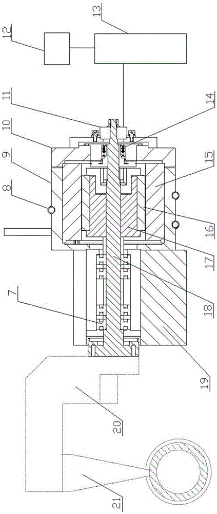
[0025] Such as figure 2 As shown, the swing grinding head driving device of the present invention includes a casing 9, which is cylindrical, with one end closed and one end open, and a cover plate 10 is arranged on the open end, the closed end of the casing 9 and the cover The plates 10 each have a central hole. There is a main shaft 18 in the casing 9, and the main shaft 18 passes through the closed end of the casing 9 and the central hole of the cover plate 10 respectively, and there is a gap between the main shaft 18 and the two central holes. A motor stator 15 is fixed on the inner wall of the casing 9 , and a motor rotor 16 is fixed on the section of the main shaft 18 in the casing 9 . The outer side of the closed end of the casing 9 is fixed with a support seat 19, the section of the main shaft 18 on the outside of the closed end of the casing 9 passes through the support seat 19, and the main shaft 18 and the support seat 19 are rotationally fitted by the bearing 7, a...

Embodiment 2

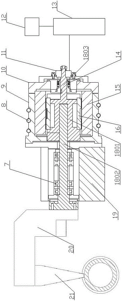
[0029] Such as image 3 As shown, the swing grinding head driving device of the present invention includes a casing 9, which is cylindrical, with one end closed and one end open, and a cover plate 10 is arranged on the open end, the closed end of the casing 9 and the cover The plates 10 each have a central hole. There is a main shaft 18 in the casing 9, and the main shaft 18 passes through the closed end of the casing 9 and the central hole of the cover plate 10 respectively, and there is a gap between the main shaft 18 and the two central holes. A motor stator 15 is fixed on the inner wall of the casing 9 , and a motor rotor 16 is fixed on the section of the main shaft 18 in the casing 9 . The outer side of the closed end of the casing 9 is fixed with a support seat 19, the section of the main shaft 18 on the outside of the closed end of the casing 9 passes through the support seat 19, and the main shaft 18 and the support seat 19 are rotationally fitted by the bearing 7, an...


PUM


Abstract

The invention relates to a driving device for a swinging grinding head. The driving device for the swinging grinding head is characterized by comprising a machine shell. The machine shell is shaped like a cylinder with a closed end and an open end, and a covering plate is arranged at the open end of the cylinder. The closed end of the machine shell and the covering plate are both provided with central holes. A main shaft is arranged in the machine shell and penetrates through the central hole of the closed end of the machine shell and the central hole of the covering plate. A motor stator is fixed to the inner wall of the machine shell. A motor rotor is fixed to the section, inside the machine shell, of the main shaft. A supporting seat is fixed to the outer side of the closed end of the machine shell. The section, on the outer side of the closed end of the machine shell, of the main shaft is rotationally matched with the supporting seat through a bearing. The end, corresponding to the covering plate, of the main shaft is connected with an encoder, the encoder is connected with a servo driver through a wire, and the servo driver is connected with a power source through a wire. The driving device is used for driving the swinging grinding head to carry out ultra-accurate grinding machining, equipment vibration is small, the angle adjustment is accurate, the grinding speed is high, the problems of crawling and inching are avoided, the machining accuracy of workpieces is high, and the maintenance cost of a mechanism is low.

Description

technical field [0001] The invention relates to a grinding device, specifically a device for driving an oscillating grinding head for superfinishing the inner and outer channels of a bearing bracket, and can also be used for superfinishing grinding of other parts of the bearing And high-speed swing motion mechanism. Background technique [0002] As we all know, bearings are an important part of modern mechanical equipment. Its main function is to support the mechanical rotating body, reduce the friction coefficient during its movement, and ensure its rotation accuracy. Therefore, during the production process of the bearing, both the inner raceway and the outer raceway must undergo super-finishing processing. Taking the processing of the outer groove of the inner bracket of the bearing as an example, when performing superfinishing processing, it is necessary to set the superfinishing grinding head on the surface of the outer groove, and use the driving device to drive the g...

Claims


Application Information

Patent Timeline
Patent Type & Authority Applications(China)
IPC IPC(8): B24B47/12B24B47/16
CPCB24B47/12B24B47/16
Inventor 许旭明
Owner 无锡天任电子有限公司
Why Eureka
Try Eureka