
Method for telecontrol telesignalling joint debugging of protective relaying device

A relay protection device, remote signaling and joint debugging technology, applied in the field of power systems, can solve problems such as high safety risks, low work efficiency, and reduced reliability, and achieve the effects of avoiding safety risks, improving work efficiency, and improving reliability.

Active Publication Date: 2016-07-06
STATE GRID FUJIAN ELECTRIC POWER CO LTD +3
View PDF4 Cites 6 Cited by
  • Summary
  • Abstract
  • Description
  • Claims
  • Application Information

AI Technical Summary

Problems solved by technology

[0005] (1) Affect the reliability of power system operation
Since the relay protection device is out of operation, for the relay protection system with two sets of configuration, there is only one set of configuration left, and the reliability is reduced; for the relay protection system of single set configuration, it is necessary to cut off the power of the primary equipment, which directly affects the power equipment normal operation
[0006] (2) High security risk
When the relay protection device is in operation, it is necessary to isolate the secondary circuit such as current, voltage, and tripping. The special debugging instrument is used for testing, and the safety risk is quite high.
[0007] (3) Work efficiency is extremely low
A 500kV substation has about 100 sets of relay protection devices. The remote control and remote signal joint commissioning time of each relay protection device is at least 1 day, and the joint commissioning cycle is quite long.
[0008] (4) A lot of soft messages in the relay protection device cannot be simulated and sent (such as abnormal sampling, EPROM error, etc.), and the joint debugging work cannot be fully completed. At present, these joint debugging work has not been carried out

Method used


Image

  • Method for telecontrol telesignalling joint debugging of protective relaying device
  • Method for telecontrol telesignalling joint debugging of protective relaying device

Examples


Embodiment Construction

[0030] The present invention will be further described below in conjunction with the accompanying drawings and embodiments.

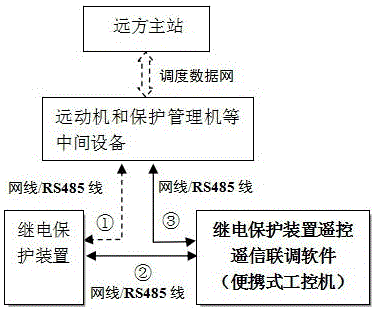
[0031] Such as figure 1 As shown, this embodiment provides a method for remote control and remote signal joint debugging of a relay protection device, including a remote master station that issues a remote operation command, and a relay protection device. The relay protection device communicates with the The remote master station is connected, and the intermediate equipment includes a remote machine and a relay protection management machine;

[0032] The structure of the relay protection device remote control, remote signaling and joint commissioning network of conventional substations is shown in the instruction manual figure 1 As shown, the remote master station issues remote operation commands, and forwards the commands to the relay protection device for operation through the remote machine and relay protection management machine; at the same time, ...


PUM


Abstract

The invention relates to a method for telecontrol telesignalling joint debugging of a relay protective device, comprising the step of adopting a relay protective device telecontrol telesignalling joint debugging software to replace the relay protective device which is running to perform telecontrol telesignalling joint debugging with the remote main station with the code table of the running relay protective device as a basic database. The method of the invention does not need to make the relay protective device exit the operation and does not need to cut the power of the primary device to finish the telecontrol telesignalling joint debugging. The accuracy can achieve 100% and the up to 90% of time can be saved. The method disclosed by the invention can improve the working efficiency, guarantees the reliable safety operation of the power grid, and solves the problem that part of the message of the relay protective device cannot be jointly debugged.

Description

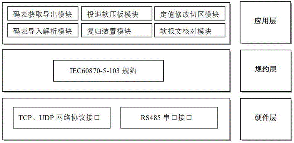
technical field [0001] The invention relates to the technical field of power systems, in particular to a method for remote-controlling, remote-signaling and joint debugging of a relay protection device. Background technique [0002] With the continuous deepening of the application of unattended conventional substations, the promotion and application of the operation of remote master stations (dispatching master stations, monitoring background or fault information master stations, etc.) of relay protection devices have been carried out in China. Mainly include: remote input / return soft pressure plate, remote reset device, remote fixed value modification and remote fixed value switching area, and remote soft message check, referred to as "remote control and remote signal joint debugging" (the same below). The transmission protocol of conventional substation relay protection devices is IEC60870-5-103. [0003] The existing remote control and remote signal joint debugging techn...

Claims


Application Information

Patent Timeline
IPC IPC(8): G01R31/327G06F17/30
CPCG01R31/3278G06F16/90
Inventor 陈建洪陈月卿邱建斌林海源陈闽江张春欣王家兴陈志辉吴芳芳
Owner STATE GRID FUJIAN ELECTRIC POWER CO LTD
Learn More