Optical component support structure, unit lens group, exposure optical system and photoetching machine

A technology for exposing optical systems and optical components, which is applied in the field of high-precision optical lens manufacturing and assembly, which can solve problems such as complex structure, difficult assembly, and occupancy, and achieve the effects of active compensation, easy processing and manufacturing, and small footprint

Inactive Publication Date: 2016-07-06
CHANGCHUN INST OF OPTICS FINE MECHANICS & PHYSICS CHINESE ACAD OF SCI
View PDF14 Cites 10 Cited by
  • Summary
  • Abstract
  • Description
  • Claims
  • Application Information

AI Technical Summary

Problems solved by technology

Patent US6392825B1 discloses a mirror frame structure with multiple elastic support units, which can offset the influence of external stress and deformation through the elasticity of the support units; since the elastic support units are processed by thin plate materials, it is difficult to achieve micron-level processing accuracy, and the elastic support The unit and the mirror frame are connected by welding or screw fastening, and the welding stress and screw preload will also reduce the final precision of the elastic support unit
Patent US6229675B1 proposes a structural form that decouples the deformation of the inner and outer frames. This structure has poor processability and is a passive compensation method. Although it can eliminate the influence of external stress on the surface shape accuracy of optical elements, it cannot compensate for dynamics. Surface error
Patent US7031082B2 discloses a mirror frame structure capable of deforming optical elements, and also equipped with a deformation monitoring unit. However, the deformation adjustment part of this structure is assembled from multiple parts, which is complex in structure and difficult to assemble and adjust. Shape tuning with nanoscale precision
Patent US7193794B2 discloses a mirror frame structure that actively compensates the surface shape error of the optical element, which can compensate the influence of astigmatism and trilobes on the imaging performance of the system without changing the spatial position of the optical element; however, this method is axially The driver or transmission structure is arranged in the direction of the optical axis, which takes up a lot of space, and it is difficult to adjust the force of the optical element at each support point, and it cannot be used for surface shape compensation of more optical elements in the same objective lens

Method used


Image

  • Optical component support structure, unit lens group, exposure optical system and photoetching machine
  • Optical component support structure, unit lens group, exposure optical system and photoetching machine
  • Optical component support structure, unit lens group, exposure optical system and photoetching machine

Examples


Embodiment Construction

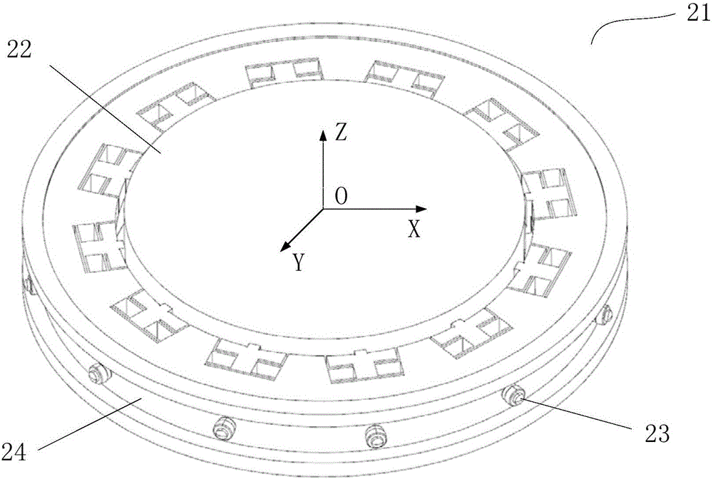
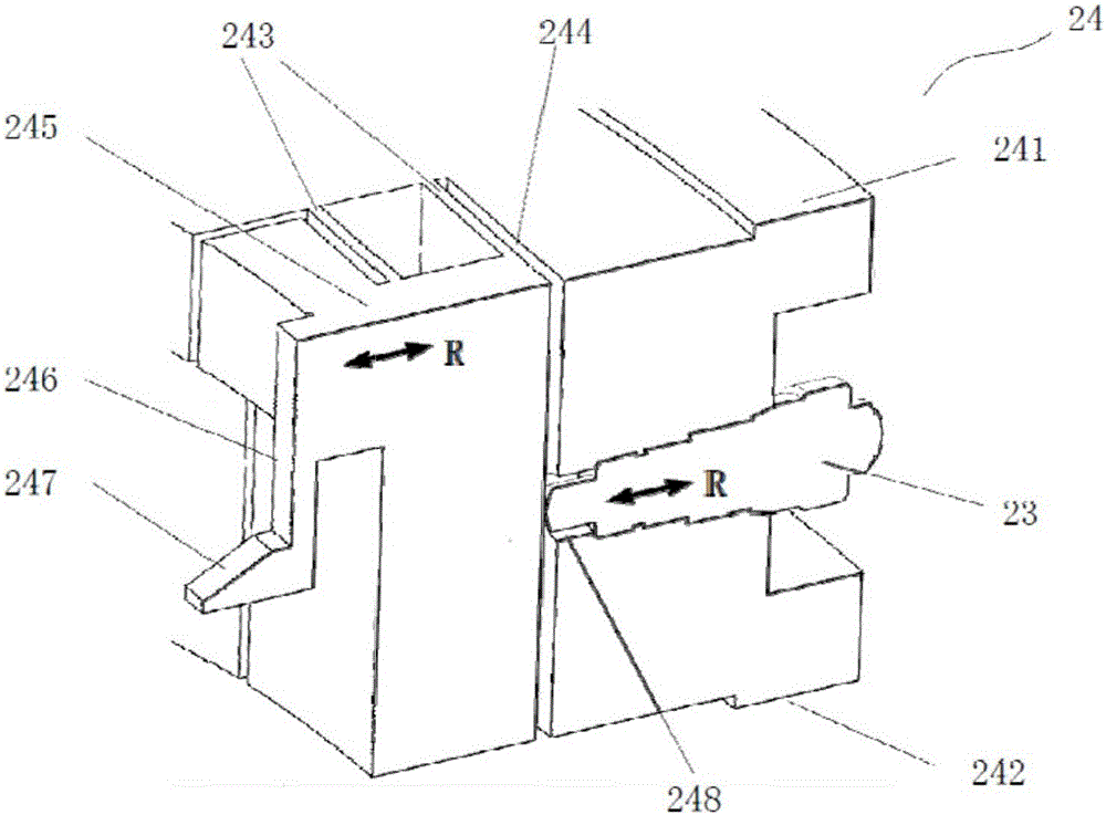
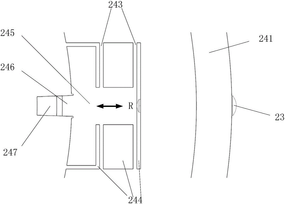
[0028] combine Figure 1 to Figure 5 , the optical element supporting structure provided by an embodiment of the present invention includes a mirror base 24 and a driving mechanism 23 . The mirror base 24 includes an upper connecting flange 241 , a lower connecting flange 242 , a guiding mechanism 243 , a slit 244 , a moving platform 245 , a supporting rod 246 , a supporting surface 247 and a positioning hole 248 which are integrally formed.

[0029] Such as figure 1, the supporting structure of the optical element is included in the unit lens group 21 , and the unit lens group 21 is usually composed of an optical element 22 , a driving mechanism 23 and a lens holder 24 . Usually, the direction parallel to the optical axis of the optical element 22 is defined as the Z axis, the center of the coordinate system is located at the center of the upper or lower surface of the optical element 22, and the plane perpendicular to the Z axis is the XY plane. The material of the optical...


PUM

PropertyMeasurementUnit
sizeaaaaaaaaaa
sizeaaaaaaaaaa
sizeaaaaaaaaaa

Abstract

The invention discloses an optical component support structure used for supporting an optical component (22) of the unit lens group (21). The optical component support structure comprises lens bases (24), wherein each lens base (24) is a mechanical member with a symmetrical circumference, a support rod (246) extends towards the center of the lens base from an inner ring of the lens base (24) and has flexibility in an optical axial direction and a radial direction of the lens base, a support surface (247) is arranged at the tail end of the support rod (246) and is matched with the lower surface of the optical component (246) so that the optical component (22) is fixed on the lens base (24), the inner side of the support rod (246) is connected with a moving table (245), the moving table (245) is connected with an outer ring of the lens base (24) through a guide mechanism (243), and the guide mechanism (243) is used for guiding the movement of the moving table (245).

Description

technical field [0001] The invention belongs to the technical field of high-precision optical lens manufacturing and assembly, and in particular relates to a support structure for an optical element capable of compensating surface shape, a unit lens group, an exposure optical system and a photolithography machine. Background technique [0002] The design, processing, manufacture and adjustment of high-end lithography projection objective lens is a very precise and complex system engineering. With the extension of Moore's Law, the semiconductor industry has higher and higher requirements for the minimum line width resolution of processor chips. In order to achieve high-quality imaging performance and higher resolution, the RMS value of the surface shape accuracy of optical components is required to reach 1nm ~2nm level. As the NA value of the projection objective optical system of the lithography machine gradually increases, the clear aperture of the optical components in th...

Claims


Application Information

Patent Timeline
Patent Type & Authority Applications(China)
IPC IPC(8): G03F7/20G02B7/02
CPCG02B7/026G03F7/70258G03F7/70825
Inventor 倪明阳华洋洋于新峰郭抗隋永新杨怀江
Owner CHANGCHUN INST OF OPTICS FINE MECHANICS & PHYSICS CHINESE ACAD OF SCI
Why Eureka
Try Eureka