
Mesh Freeform Surface Annular Tool Path Planning Method Based on Improved Butterfly Subdivision

A tool path, improved technology, applied in the field of milling, can solve problems such as poor tool path continuity

Active Publication Date: 2018-09-07
ZHEJIANG UNIV
View PDF3 Cites 4 Cited by
  • Summary
  • Abstract
  • Description
  • Claims
  • Application Information

AI Technical Summary

Problems solved by technology

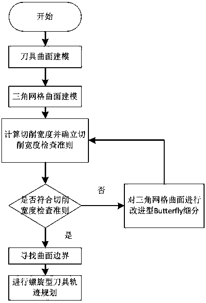
[0005] In order to solve the problem of poor continuity of generated tool trajectories in tool trajectory planning, the present invention provides a method for planning tool trajectories based on improved Butterfly subdivision grid free-form surface rings

Method used


Image

  • Mesh Freeform Surface Annular Tool Path Planning Method Based on Improved Butterfly Subdivision
  • Mesh Freeform Surface Annular Tool Path Planning Method Based on Improved Butterfly Subdivision
  • Mesh Freeform Surface Annular Tool Path Planning Method Based on Improved Butterfly Subdivision

Examples


Embodiment

[0106] use Figure 7 The triangular mesh model of the face shown is used to verify the circular tool trajectory planning method based on the improved Butterfly subdivision triangular mesh surface. The face STL model contains a total of 879 vertices and 1689 triangular patches. It has concave surface features and convex surface features, and the curvature changes greatly. It can effectively verify the triangular mesh surface ring tool trajectory planning method based on the improved Butterfly subdivision.

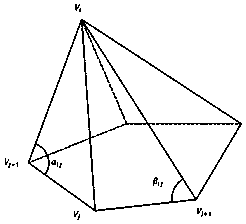
[0107] (1) First, analyze the surface features of the STL model of the face, and first solve the curvature of each vertex of the STL model. Each vertex on the surface and its adjacent vertices form a facet triplet, and each vertex V i The triplet corresponding to the patch pair V i Curvatures are affected at and include the vertex V i The larger the area of ​​the triangle surface, the vertex V i The greater the influence of the curvature, then to contain the vertex V i T...


PUM


Abstract

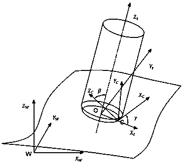
The invention discloses a grid free-form surface toroidal cutter path planning method based on improved Butterfly subdivision. The method comprises the steps of toroidal cutter surface modeling and triangular grid free-form surface modeling. Besides, the cutter surface of a cutter contact point (CC point) and a workpiece surface are geometrically analyzed with combination of the geometrical features of the toroidal cutter. The minimum front inclination angle of the cutter is calculated according to the principle of cutting cutter interference so as to obtain the maximum width of a cutting path, based on which subdivision is performed on the triangular grid surface by adopting the improved Butterfly subdivision method so that the line space of the cutter path is enabled to meet the width requirement of the cutting path. Planning of the spiral cutter path cutter contact point (CC point) is performed line by line along the boundary of the triangular grid with a surface contour curve acting as an initial cutter path so that the position of a cutter center (CL point) is finally solved according to the toroidal cutter geometrical model. The method is applied to high-speed machining so that continuity of the formed cutter path can be enhanced, cutter load fluctuation can be reduced, and cutting stability can be enhanced and the service life of the cutter can be prolonged under the premise of guaranteeing the cutting quality.

Description

technical field [0001] The invention belongs to the field of milling processing, and more specifically relates to a method for planning a free-form circular tool trajectory on a triangular grid free-form surface based on an improved Butterfly subdivision. technical background [0002] Freeform surfaces are widely used in product design fields such as aerospace, automobiles, and ships, and are of great significance to tool trajectory planning for freeform surface processing. Freeform surfaces can be represented by parametric patches and polygonal patches. However, accurate modeling of parametric patches is difficult, and the splicing and segmentation of parametric patches are prone to interference and gaps, the steps are cumbersome, and the amount of calculation is large. However, polygonal patches, especially triangular patches, have simple segmentation and splicing criteria and high robustness. There is no high-order curve intersection operation in surface intersection ope...

Claims


Application Information

Patent Timeline
Patent Type & Authority Patents(China)
IPC IPC(8): G05B19/19
CPCG05B19/19G05B2219/35097
Inventor 冯毅雄王琪瑞程锦
Owner ZHEJIANG UNIV
Learn More